


continued. . .continued. . .
11
☞
8
☞
signal through external processors with a crossover circuit of their own,
such as the new digital units. Simply move the switch to SUBWOOFER
DIRECT to disengage the built in crossover. For all other installations
which do not have a separate electronic crossover, we recommend you
leave the switch set to INTERNAL X-OVER to provide optimum
performance.
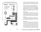
Auto turn on function
With this function in the "auto" position, your subwoofer can be safely
left with the main power switch on continuously. The subwoofer will turn
itself on automatically when an audio signal is present. If no signal is
present for approximately 10 minutes, the unit will switch to standby mode.
While in standby mode, your subwoofer will draw very minimal power.
This function can be disabled by leaving the switch in the "on" position.
Power switch
The master power switch is located on the lower half of the unit. This rocker
style switch is the main on/off for the unit. This switch should be set to
position 1 (up) for on, and 0 (down) for off. If the unit is to be left unused
for an extended period of time, the master power switch should be turned
off.
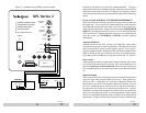
Subwoofer outputs
The Velodyne subwoofer is designed to operate using the full range audio
signal for input when using the built-in crossover. Some processors/
receivers, have a "subwoofer out" jack that is internally filtered and
designed to be used with a conventional amplifier and speaker. In some
rare cases, combining both an external crossover and the one internal to
the subwoofer may result in low output and increased noise. In these
installations you may need to bypass the internal crossover in either the
processor or Velodyne subwoofer. In some installations, simply setting
one crossover to a higher frequency (such as 120 Hz) will restore maximum
performance. To bypass the subwoofer's internal crossover when the unit
between the subwoofer and your main speakers/amplifier. To adjust,
simply listen to the system with music playing. Then move the switch from
one position to the other and listen for a change in low frequency output.
The correct position will have a greater amount of apparent low frequency
output.
Crossover switch - INTERNAL X-OVER/SUBWOOFER DIRECT
This switch allows the electronic crossover circuitry to be removed from
the signal path. This is required in certain installations which route the
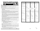
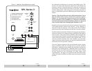
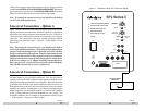
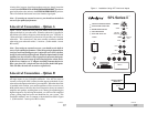
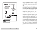
Figure 2. Installation Using Stereo Line-level Inputs
AMPLIFIER
MAIN OUTPUTS
RIGHT LEFT
TO SATELLITE SPEAKERS
PRE-AMP
MAIN OUTPUTS
MAIN INPUTS
LEFT RIGHT
RIGHT
LEFT
+ R - - L +
SPEAKER LEVEL
OFF
POWER
ON
LOW-PASS
CROSSOVER
40 Hz
80 Hz
120 Hz
SUBWOOFER
VOLUME
MIN
MAX
WARNING: TO REDUCE THE RISK OF FIRE
OR ELECTRIC SHOCK. DO NOT EXPOSE
THIS APPLIANCE TO RAIN OR MOISTURE.
RISK OF ELECTRIC
DO NOT OPEN
CAUTION
AVIS:
RISQUE DE CHOC ELECTRIQUE-NE PAS OUVRIR
0
180
PHASE
0
0
POWER
ON
AUTO
LONG THROW DRIVER
HIGH-TEMP VOICE COIL
1000 WATTS CONTINUOUS POWER
DYNAMIC DRIVER CONTROL
ULTRA EFFICIENT CLASS D AMP
SUBWOOFER
DIRECT
INTERNAL
X-OVER
117V~
60Hz
8A
OUTPUT
INPUT
R
L
LFE
WARNING: TO REDUCE THE RISK OF FIRE
OR ELECTRIC SHOCK. DO NOT EXPOSE
THIS APPLIANCE TO RAIN OR MOISTURE.
RISK OF ELECTRIC
DO NOT OPEN
CAUTION
AVIS:
RISQUE DE CHOC ELECTRIQUE-NE PAS OUVRIR
VELODYNE ACOUSTICS, INC.
SERIAL #
SPL Series
TM
II
I
O