


5
☞
5
☞
(6) HIGH PASS CROSSOVER Switch
This switch selects the frequency for the high pass crossover.
This crossover is functional on both line and speaker-level
outputs. Smaller speakers with limited low frequency output may
perform better using the higher 100 Hz setting that will reduce the
low frequencies sent to them. Larger speakers with greater low
frequency output may be able to handle the 80 Hz setting without
strain.
(7) SPEAKER LEVEL INPUT Terminals
Connect these input terminals to the speaker output terminals
of your amplifier or receiver. If you use this method of
connection, when you go to the receiver speaker set up menu,
make sure you select the large speaker option.
(8) SPEAKER LEVEL OUTPUT Terminals
Sends a crossed-over speaker-level signal to the front speakers.
See below for a more detailed explanation of this crossover.
Rear Panel Connections – Detailed Explanation
Your new subwoofer is equipped with both speaker-level and line-
level inputs. Use the RCA/Phono type “INPUT” jacks when connect-
ing your subwoofer to a pre-amp, signal processor, or line-level
crossover. The “SPEAKER LEVEL INPUT” jacks connect directly
to the speaker outputs of an integrated amplifier or receiver. Your
amplifier section will notice no additional loading effects when you
use these inputs because of their high impedance.
Note:
Do not use both the RCA/Phono “INPUT” connections and “SPEAKER
LEVEL INPUT” connections simultaneously.
Low-Pass Crossover
Both sets of inputs sum the left and right channels together and the
resulting signal is passed through an adjustable low-pass crossover
before being amplified. The crossover control allows you to adjust
the upper limit of the subwoofer’s frequency response from 40 to
120 Hz. The subwoofer’s response will begin rolling off above the
frequency you set this control to.
(7) Bornes ENTRÉE NIVEAU HAUT-PARLEUR
Connectez ces bornes d’entrée aux bornes de sortie des haut-
parleurs de votre amplificateur ou de votre récepteur. Si vous utilisez
cette méthode de branchement, quand vous allez au menu de
réglage des haut-parleurs du récepteur, assurez-vous que vous
sélectionnez l’option gros haut-parleurs.
(8) Bornes SORTIE NIVEAU HAUT-PARLEUR
Ceci envoie un signal de niveau de haut-parleur filtré. Aux haut-
parleurs avant. Lisez l’explication plus détaillée du filtre passif ci-
dessous.
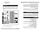
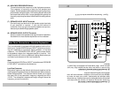
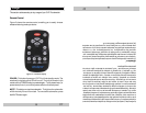
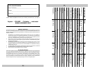
Figure 1. Connexions au panneau arrière du CHT-R
VOLUME
UP
DOWN
HIGH-PASS
CROSSOVER
80 Hz
100 Hz
LOW-PASS
CROSSOVER
40 Hz
80 Hz
DIRECT
SPEAKER LEVEL INPUT
SPEAKER LEVEL OUTPUT
OUTPUT
INPUT
R
L
LFE IN
LEFTRIGHT
OFF
ON
POWER
CHT-R Series
RISK OF ELECTRIC SHOCK
DO NOT OPEN
CAUTION
WARNING: TO REDUCE THE RISK OF FIRE
OR ELECTRIC SHOCK. DO NOT EXPOSE
THIS APPLIANCE TO RAIN OR MOISTURE.
AVIS:
RISQUE DE CHOC ELECTRIQUE-NE PAS OUVRIR
DOUBLE INSULATION - WHEN SERVICING USE ONLY IDENTICAL REPLACEMENT PARTS
VELODYNE ACOUSTICS, INC.
SERIAL #
AUTO ON/OFF
ACTIVE
INACTIVE
230V~
50Hz
F 1A L
1
2
6
7
8
4
3
5