


Quick Start Guide
TCX series
TCX Series Quick Start Guide v1.1 - Page - 3
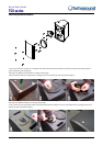
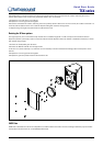
Wall brackets
Illustrated: TCX-12 on a WB-55 wall bracket
• Separate the component parts of the bracket into the wall plate and speaker plate
assemblies by removing the nylock nut underneath the wall plate horizontal lug.
• Remove the countersunk bolts on the rear panel of the cabinet and attach the speaker
plate to the cabinet with the bolts supplied.
• Fix the wall plate in the venue using appropriate fixings (not supplied), ensuring that the
cable access hole is towards the top.
• Lift the loudspeaker on to the wall plate and locate the large captive bolt welded to the
speaker plate through the wall plate lug. Re-assemble the bracket parts, adjust the aim of
the loudspeaker and tighten all bolts.
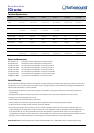
Ceiling brackets
Illustrated: TCX-12 on a CB-55 ceiling bracket
• Separate the component parts of the bracket into the ceiling plate and speaker plate
assemblies by removing the nylock nut underneath the wall plate lug.
• Remove the countersunk bolts on the rear panel of the cabinet and attach the speaker plate
to the cabinet with the bolts supplied.
• Fix the ceiling plate in the venue using appropriate fixings (not supplied). Lift the
loudspeaker on to the ceiling plate and re-assemble the bracket fixings, adjust the aim of
the loudspeaker and tighten all bolts.
Pole brackets
TCX series mid-high cabinets equipped with a recessed pole mount socket can be wall mounted with the generic PB-55 pole
bracket. Fix the bracket in the venue using appropriate wall fixings, mount the loudspeaker on to the spigot, and aim the
loudspeaker as required. Tighten the pole bracket grub screw to lock the loudspeaker and prevent unauthorised removal.
OmniMount™ brackets
The internal rigging points are also compatible with OmniMount™ series 120 wall and ceiling brackets. To mount TCX cabinets
with OmniMount™ brackets follow the instructions provided with the brackets.
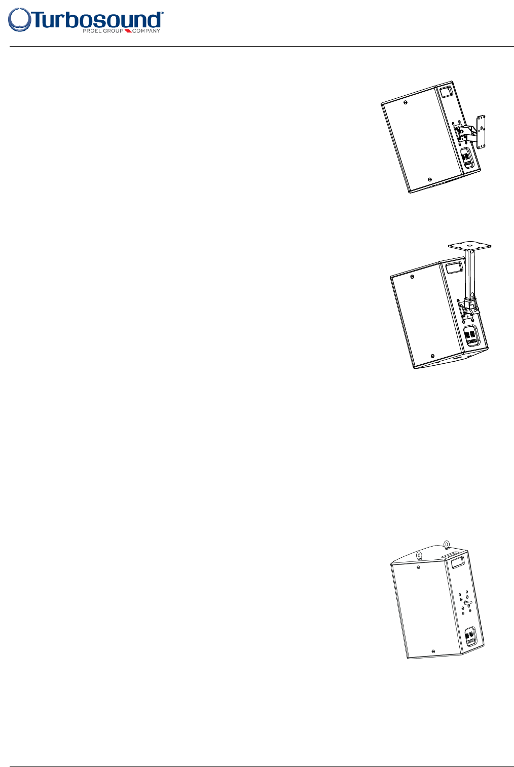
Suspending with eyebolts
Illustrated: TCX-15 with M10 eyebolts
TCX cabinets can be suspended using optional eyebolts coupled to the internal rigging points
provided on the top, bottom and sides and back. The simplest method is to use the two
rigging points on the top and a single pull-back rigging point in the centre of the rear panel.
Remove the appropriate countersunk screws and replace them with shoulder eyebolts, which
must have a thread length of at least 18mm. Use the rear rigging point to angle the cabinet
for optimum room coverage. Cabinets may be hung upside down if required.
IMPORTANT NOTE: The mounting of a permanently installed sound system may be
dangerous unless undertaken by qualified personnel with the required experience and
certification to perform the necessary tasks. Walls, floors or ceilings must be capable of safely and securely supporting the actual
load. The mounting accessory used must be safely and securely fixed both to the loudspeaker and to the wall, floor or ceiling.
When mounting rigging components on walls, floors or ceilings, ensure that all fixings and fasteners used are of an appropriate
size and load rating. Wall and ceiling claddings, and the construction and composition of walls and ceilings, all need to be taken
into account when determining whether a particular fixing arrangement can be safely employed for a particular load. Cavity plugs
or other specialist fixings, if required, must be of an appropriate type, and must be fitted and used in accordance with the maker’s
instructions.