


Quick Start Guide
TCS series
TCS Series Quickstart Guide - Page - 5
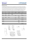
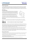
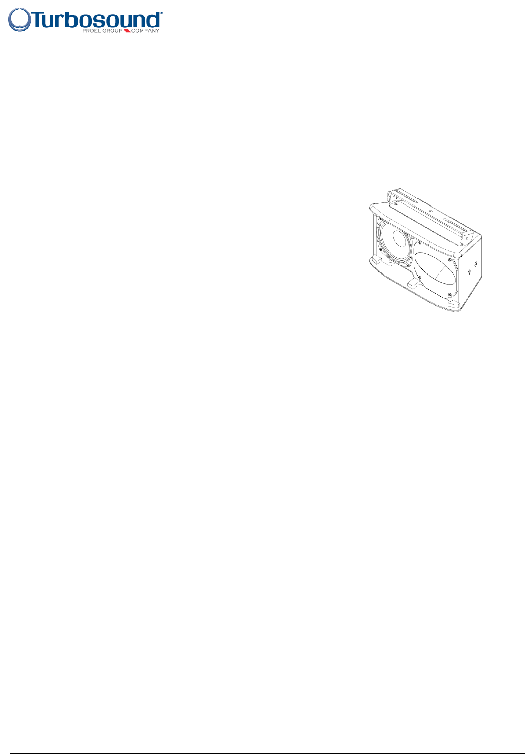
Wall and ceiling brackets
To install a loudspeaker using Turbosound wall and ceiling brackets, first separate the brackets into their wall/ceiling
plate and speaker plate component parts. Remove the countersunk bolts on the rear panel of the cabinet. Attach the
speaker plate to the cabinet with the bolts supplied. Fix the wall/ceiling plate in the venue using appropriate fixings
(not supplied). Lift the loudspeaker on to the wall plate and re-assemble the bracket parts, adjust the vertical angle and
tighten all bolts.
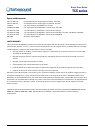
Downfill Applications
The TCS-61 can be tight-packed underneath TCS-122 or TCS-152 cabinets to
provide downfill coverage using the SB-61 swivel bracket. First disassemble
the swivel bracket into its component parts. Remove the countersunk bolts
from the bottom panel of the TCS-122/152 cabinet and fit the section with the
elongated holes using the fixings supplied. Remove the countersunk bolts on
the top panel and fit the swivel bracket using the supplied fixings. Re-
assemble the swivel bracket, angle as appropriate and tighten all fixings.
To use the SB-61 in a ceiling-mount application, separate the component
parts as above, fix the top section to the ceiling with appropriate fixings (not
supplied). Fit the other half to the cabinet, re-assemble the bracket, angle as appropriate and tighten all fixings.
Vertical Arrays
An array of two or more cabinets requires the use of flyplates and inter-cabinet couplers, which are assembled
together in a ‘daisy chain’ fashion to build up the required array. These are supplied as kits including appropriate
fixings:
07G0335 FP-1 KIT kit of two FP-1 flyplates (one left, one right) for TCS-122 or TCS-152 mid/highs
07G0340 FP-2 KIT kit of two FP-2 flyplates (one left, one right) for TCS-B15A or TCS-B15B subs
IMPORTANT NOTE: The rigging of a flown sound system may be dangerous unless undertaken by qualified personnel
with the required experience and certification to perform the necessary tasks. Fixing of hanging points in a roof should
always be carried out by a professional rigger and in accordance with the local rules of the venue. Walls, floors or
ceilings must be capable of safely and securely supporting the actual load. The rigging accessory used must be safely
and securely fixed both to the loudspeaker and to the wall, floor or ceiling.
When mounting rigging components on walls, floors or ceilings, ensure that all fixings and fasteners used are of an
appropriate size and load rating. Wall and ceiling claddings, and the construction and composition of walls and
ceilings, all need to be taken into account when determining whether a particular fixing arrangement can be safely
employed for a particular load. Cavity plugs or other specialist fixings, if required, must be of an appropriate type, and
must be fitted and used in accordance with the maker’s instructions.
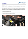
Rotating the HF horn pattern
The high frequency horn in all TCS-122 and TCS-152 models can be rotated through 90° in order to swap the horizontal
and vertical dispersion patterns, particularly useful when assembling clusters or for example to retain the original
dispersion when the cabinet is installed in a horizontal orientation.
1. Place the cabinet on its back on a suitable work surface. Remove the four pan-head posidrive screws that hold the
grille in place and set the grille aside (fig 1).
2. Remove the bass driver and horn fixings screws (fig 2).
3. Disconnect and remove the bass driver, making a note of the polarity for later reconnection (fig 3).