


Arraying and Rigging
TCS series
TCS series Arraying and Rigging - Page 2
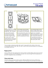
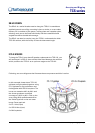
In this example the TCS-122/94
loudspeakers with horns in the
standard 90° x 40° orientation
are tight packed vertically
horn-to-horn, providing a
combined coverage of 90°
horizontal by approximately
80° vertical, with a useful
vertical beam and a mid-range
lobe that projects well down a
longer, thinner room.
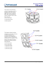
The HF horns in this horizontal
array of TCS-122/94 boxes have
been rotated to give individually
40° horizontal by 90° vertical. The
horizontal coverage patterns add
up to give combined dispersion
of 120° horizontal by 90° vertical.
This example shows how the
same coverage pattern as the
vertical array on the far left can
result from a completely
different physical array. The HF
horns are rotated to give 40°h x
90°v and then the whole array
is assembled horizontally to
give combined coverage of 90°
horizontal by 80° vertical.
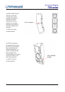
These examples are based on the 90° x40° model. If using the 60° x40° models, a further three
coverage pattern options of 60° x 80°, 120° x 60°, and 60° x 80° would be available to you, depending
on the shape of the room.
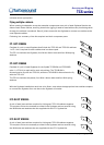
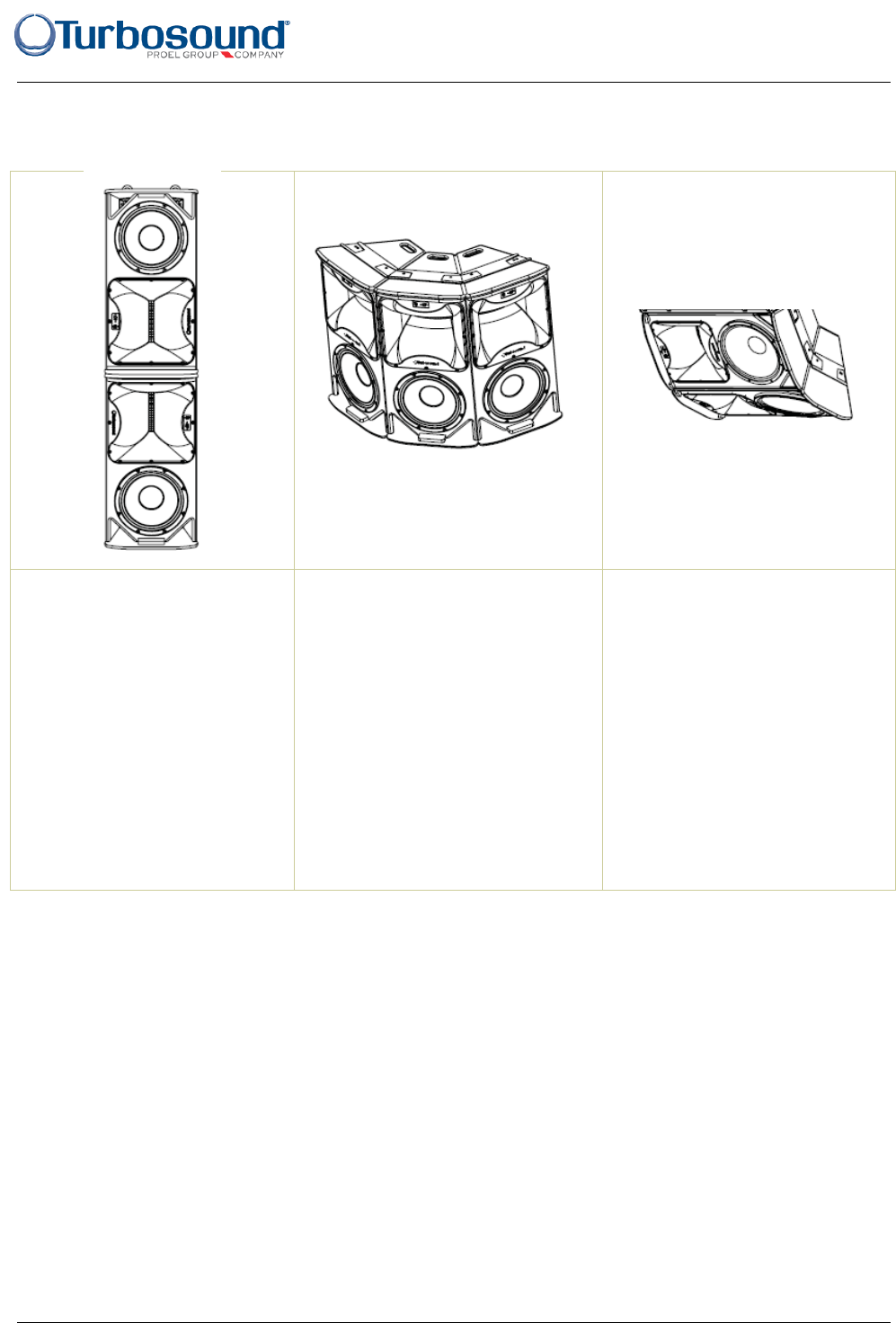
Rigging options
All of the TCS boxes have rigging points on the top, bottom and both sides, so they can be mounted
practically any way you like. For example, one option is to mount a single TCS-122 upside down to
get the HF waveguide closer to the audience.
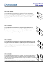
Flying single boxes
This can be simply achieved with M10 eyebolts, WB-20 and WB-55 wall brackets, CB-55 ceiling
brackets, and OmniMount™ speaker brackets, for which bolt patterns are provided on the back of the