Quick Start Guide
TCS series
TCS series Quickstart Guide v1.0 - Page - 4
Flying system components have been individually tested in accordance with the following regulations:
• The Health and Safety at Work Act 1974
• The Supply of Machinery (Safety) Regulations 1992
• The Lifting Operations and Lifting Equipment Regulations 1998
General Description
To take full advantage of the extremely flexible properties of the TCS series loudspeaker, the rigging system is designed
to be intuitive, inherently safe, flexible, and simple to use. The load is taken entirely through the steel flygear and not
through the cabinet’s woodwork.
Rigging Parts
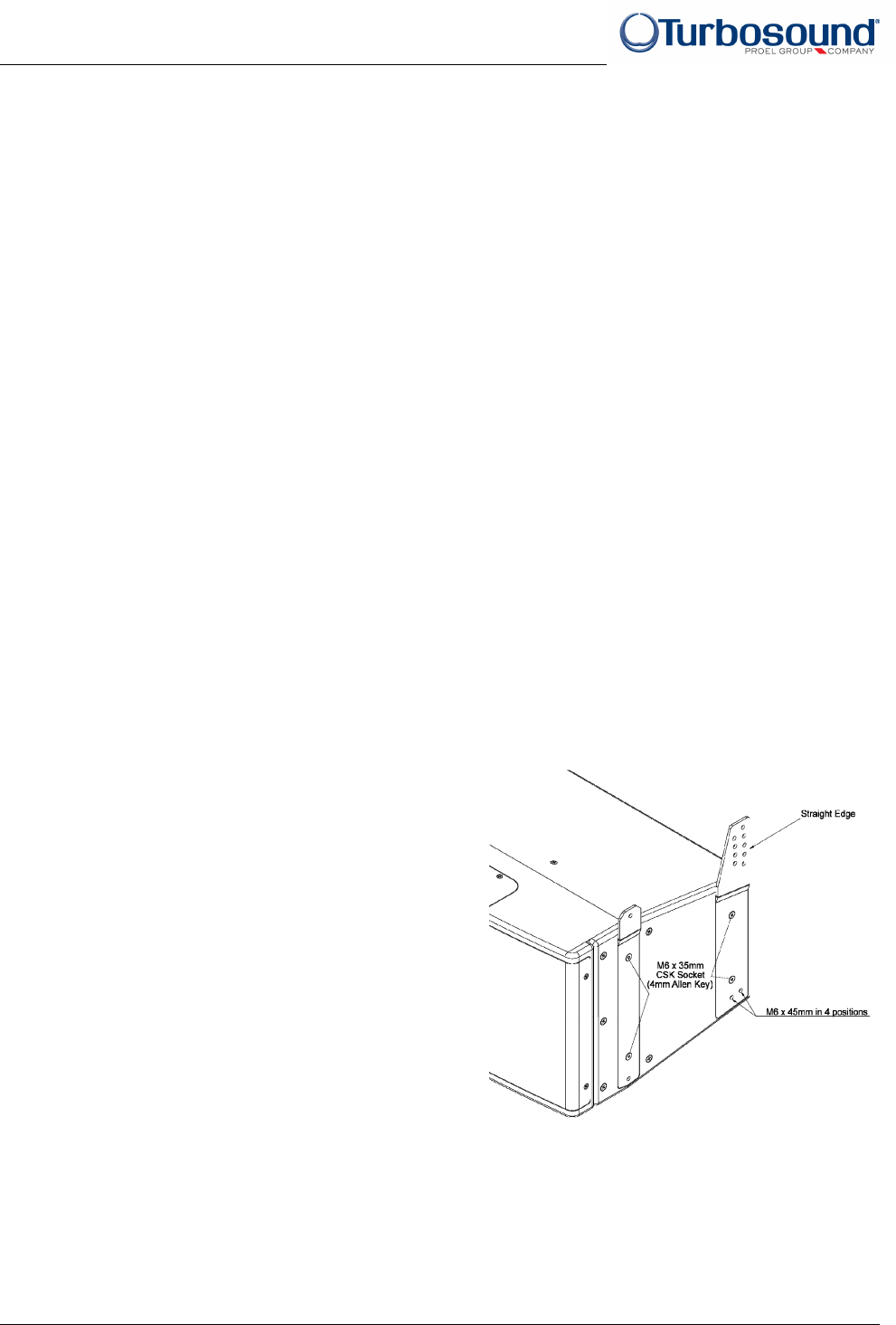
The rigging system consists of external steel flyplates fitted into rebates on the short sides of the loudspeaker enclosure
forming the pivot point about which cabinets can be angled, working together with flyplates fitted towards the rear of
the cabinet which mate with the flyplates of the cabinet above, providing a range of inter-cabinet angles.
A kit of parts is supplied with each TCS-1061 loudspeaker cabinet, consisting of:
8 x M6 x 35mm csk hex head screws
2 x front flyplate
2 x rear flyplate (handed left and right)
4 x M6 x 45mm high tensile socket head screws
4 x M6 split washers
1 x 4mm Allen key
1 x 5mm Allen key
The rigging system includes all the necessary
hardware to support a column of up to 5 cabinets
(using the FK-1061 flying kit), or up to 16 cabinets
(using the FB-1061 flying grid).
The rigging design allows the creation of arrays that
can be assembled quickly and with full control of the
vertical angles between enclosures and the array’s
vertical inclination. A range of inter-cabinet angle
adjustment is provided in 2° increments from 0° to
16°.


