


user manual
TA-500
TA-500 user manual
Page 66
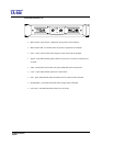
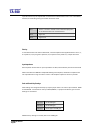
of performance may be experienced if connected to unbalanced sources. If it is unavoidable,
however, the following wiring convention should be used.
Pin 1 Screen - connect to chassis of the unbalanced equipment,
or left disconnected at the unbalanced end
Pin 2 signal hot
Pin 3 Signal cold
Polarity
In accordance with international standards, T series amplifiers are supplied with Pin 2 hot (+),
so a positive (+V) input gives a positive (+V) output from the positive (+) output terminals.
Input Impedance
Each amplifier channel has an input impedance of 10kΩ, seen between pins 2 & 3 of the XLR.
When used with the LMS-D6 Loudspeaker Management System, distribution amplifiers are
not required when a large number of T-25 or T-45 amplifier inputs are driven in parallel.
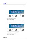
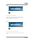
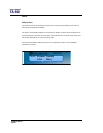
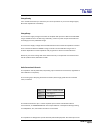
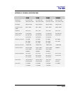
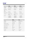
Gain and Sensitivity Settings
Gain settings are changed internally by simple jumper links. Two rows of pins marked - GAIN
A and GAIN B - are situated on the input PCB (PCB701). A jumper link sets the gain and the
settings are as follows:
Link 1 & 2 Gives 32dB gain
Link 3 & 4 Gives 26dB gain
Link 2 & 3 Gives approx 37.5dB gain
NOTE: Factory setting is normally link 1 & 2 = 32dB gain.