


user manual
TA-500
TA-500 user manual
Page 46
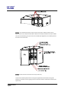
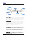
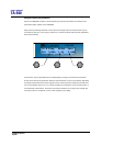
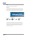
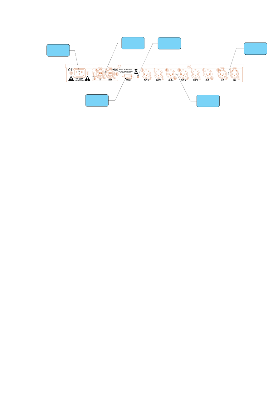
Rear Panel Functions
Power Inlet
Network Card
Audio Output
Connectors
Audio Input
Connectors
Secure Mode
Switch
Serial Comms
Port
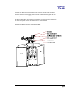
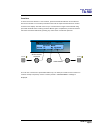
Power Inlet – provides connection to a suitable mains electricity supply using the cable
supplied. The controller has a switch mode power supply that is capable of operating with a
nominal mains voltage of 80 to 240v, 50/60Hz without re-configuration.
Network card – connects to a PC via a BvNet interface to enable network control of the
loudspeaker system.
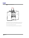
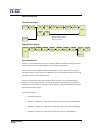
Audio Input connectors – these are fully balanced and are wired pin 1 ground, pin 2 hot and
pin 3 cold. The two inputs have pin 1 connected directly to the chassis and feed the signal
processing chains. If an unbalanced source is used, a connection should be made between
the pin 3 ‘cold’ signal and the ground connection of the unbalanced source.
Audio Output connectors – the processed outputs are impedance balanced, and are wired
pin 1 ground, pin 2 hot and pin 3 cold. An unbalanced input may be driven by by connecting
pin 3 ‘cold’ signal to the ground connection of the unbalanced destination input. Note that
output pin-1’s are ground lifted at audio frequencies but connected to ground at RF for good
EMC performance. The intention being that the amplifiers the processor is driving should be
responsible for the grounding of their input cable shields.
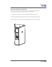
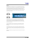
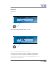
Communications port connector – the unit may be controlled entirely from another
controller (typically a Personal Computer), running an application that is compliant with the
ObCom standard. Connection will normally be made to the controller via this serial port
connector. This port is also used for updating the firmware in the unit.
Note: The communications port is NOT disabled when the front panel is made secure using
the secure button.