


24
4
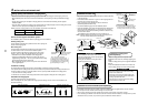
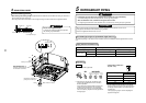
DRAIN PIPING WORK
REQUIREMENT
• Ensure insulating of the drain pipes and connecting parts on the indoor units.
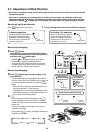
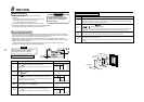
• The drain pipe should have a downward slope of at least 1/100 and ensure
there are no swells or blockages as this will cause abnormal sounds.
• The maximum traverse length of drain pipe is 20 m. Provide support
brackets at intervals of 1.5 to 2 m where necessary to prevent movement.
• Install the combined piping as shown in the illustration.
• Do not create an air purge in the pipework,
as the water would leak from this point.
• The hard vinyl-chloride pipe cannot be connected
directly to the drain pipe connecting port of the indoor unit.
For connection with the drain pipe connecting port,
ensure that the supplied flexible hose is fitted.
• Adhesive agent cannot be used for the pipe
connecting port (hard socket) on the indoor unit.
Be sure to use the supplied hose band for fixing,
otherwise there is a risk of damage or water
leakage from the drain pipe connecting port.
CAUTION
• Install the drain piping so that the water
drains effectively.
• Apply heat insulation to prevent dew
condensation from forming.
• Incorrectly installed pipe work may result
in a water leak.
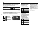
Pipe material/Insulator and size
The following materials for piping work and insulation
are to be procured locally.
Trap
Arched
shape
Support
bracket
1/100 or more
downward
Heat
insulator
1.5m to 2m
NO
GOOD
As long as possible (10cm)
VP30 or more
Downward slope
1/100 or more
VP25
VP25
VP25
(Collective pipes)
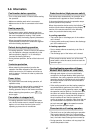
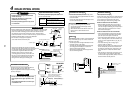
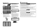
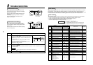
Connection of flexible hose
• Insert the soft socket of the supplied flexible hose
into the connecting port of the drain pipe.
• Align the supplied hose band to the pipe connecting
port end, and tighten.
REQUIREMENT
• Fix the soft socket with the supplied hose
band, tighten at the upper position of the
unit.
• The supplied flexible hose can bend up to
a maximum of 45°
Attached hose band
Attached flexible hose
Drain pipe connecting port
(Hard socket)
VP25 vinyl chloride pipe
(Procured locally)
Adhesive agent prohibited
Soft socket Hard socket
Socket for VP25
(Procured locally)
Riser (Trap)
90˚ Bend
max
45˚
max
45˚
OK
NO GOOD
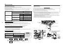
Socket for VP25 vinyl chloride pipe
(To be local procure)
Align the attached hose band to the
end of hose, set the tightening
position upward, and then tighten it.
Indoor unit body
Drain pipe
connecting port
(Transparent)
Flexible hose
(Accessory)
VP25 vinyl chloride pipe
(To be local procure)
Pipe material
Insulator
Hard vinyl chloride pipe socket for VP25
Hard vinyl chloride pipe VP25
(Outer diameter Ø32 mm)
Foamed polyethylene foam, thickness:
10 mm or more
Connection of drain pipe
• Connect the hard socket (Procured locally) to the
hard socket side of the supplied flexible hose which
has been installed.
• Connect the drain pipes (Procured locally) in turn to
the connected hard sockets.
REQUIREMENT
• Using an adhesive agent for vinyl chloride,
connect the hard vinyl chloride pipes so that
water does not leak.
• Allow sufficient time for the adhesive to set and
harden. (Refer to the instructions of the
adhesive.)
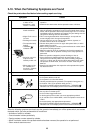
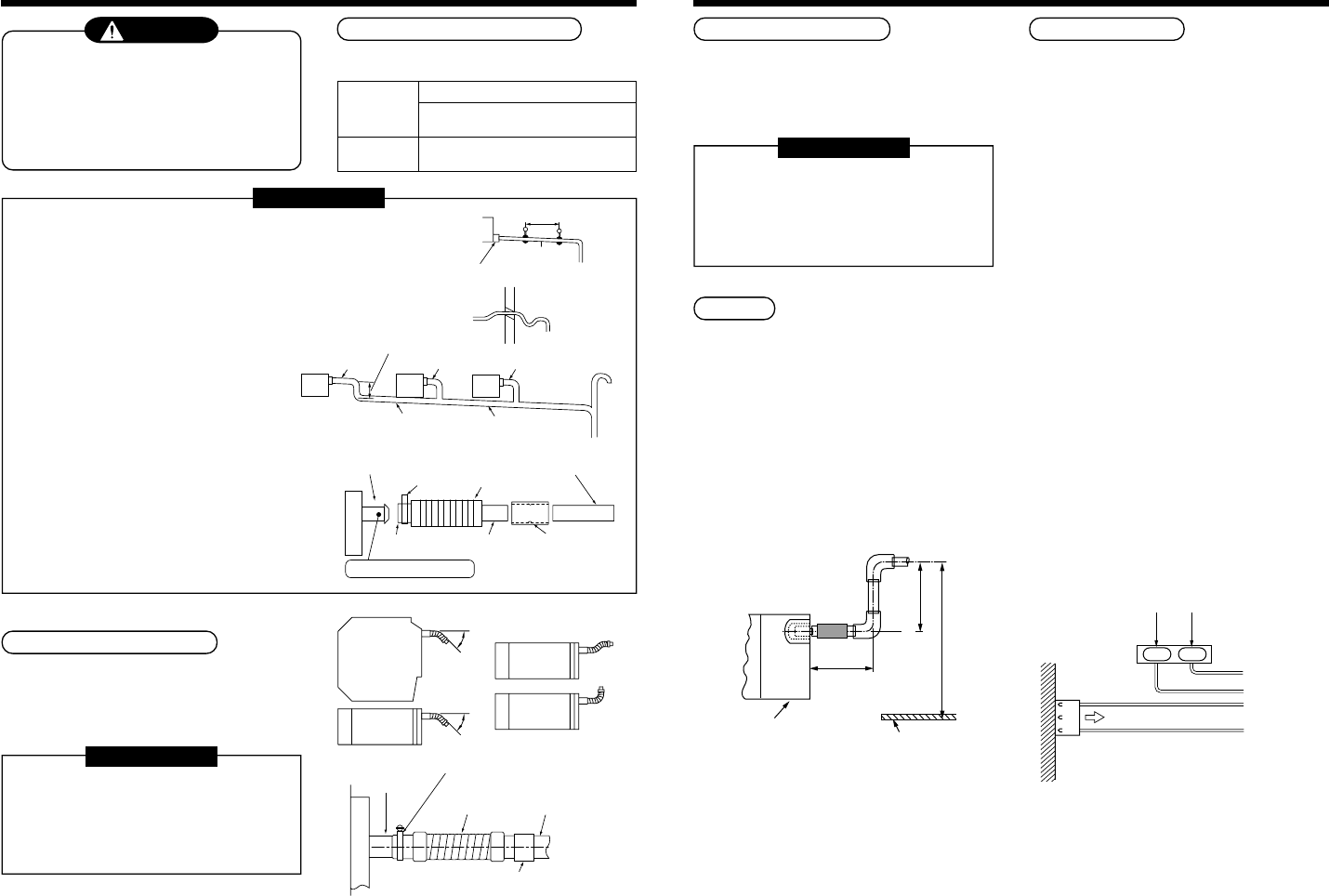
Drain up
When it is not possible to achieve a natural downward
slope on the drain pipe, you can create a vertical lift
(Drain up) on the pipe.
• Set the height of the drain pipe within 850 mm from
the bottom surface of the ceiling.
• The drain pipe should be piped from the drain pipe
connecting port horizontally for a maximum of
300 mm and then piped vertically.
• After piping the vertical lift, ensure the pipe work is
set to a downward gradient.
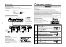
Check the draining
After completion of drain piping,
Check water drains away and that no water leaks from
any of the connecting parts. At the same time check
for any abnormal sounds from the drain pump.
Ensure drainage is checked during cooling mode.
When the electric work has finished:
• Before installing the ceiling panel, pour water as
shown in the following figure, check water drains
from the drain pipe connecting port (Transparent) in
COOL mode and then check there are no water
leaks from the drain pipes.
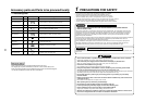
When the electric work has not finished:
• Pull out the float switch connector (3P: Red) from
P.C. board connector (CN34: Red) of the electric
parts box. (Ensure the power is turned off.)
• Connect the single-phase 220-240V, 1N, 50Hz (or
220V, 1N, 60Hz) power to the terminal blocks R (L)
and S (N). (Never apply 220-240V to (A), (B), (U1)
and (U2).)
• Pour water referring to the next page figure.
(Amount: 1500 cc to 2000 cc)
• When the power is turned on, the drain pump motor
drives automatically. Check water is drained from
the drain pipe connecting port (Transparent), and
then check there is no water leak from the drain
pipes.
• After checking for water leaks on the drain, turn off
the power supply, and re-attach the float switch
connector to the original position (CN34) on the P.C.
board and refit the electric parts box.
Rising up
627.5mm or less
Rising up 850mm or less
300mm
or less
Indoor unit
Underneath of ceiling
220–240V, 1N ~, 50Hz
220V 1N ~, 60Hz
White
Black
CN34
(RED)
Black
Red
Pull out connector CN34 (Red) from P.C. board.
R(L) S(N)