


7
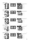
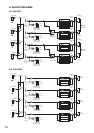
DA-550F
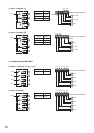
DA-500FH
7
9
12
98
1110 10
7
9
12
98
11
6
6
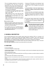
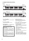
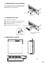
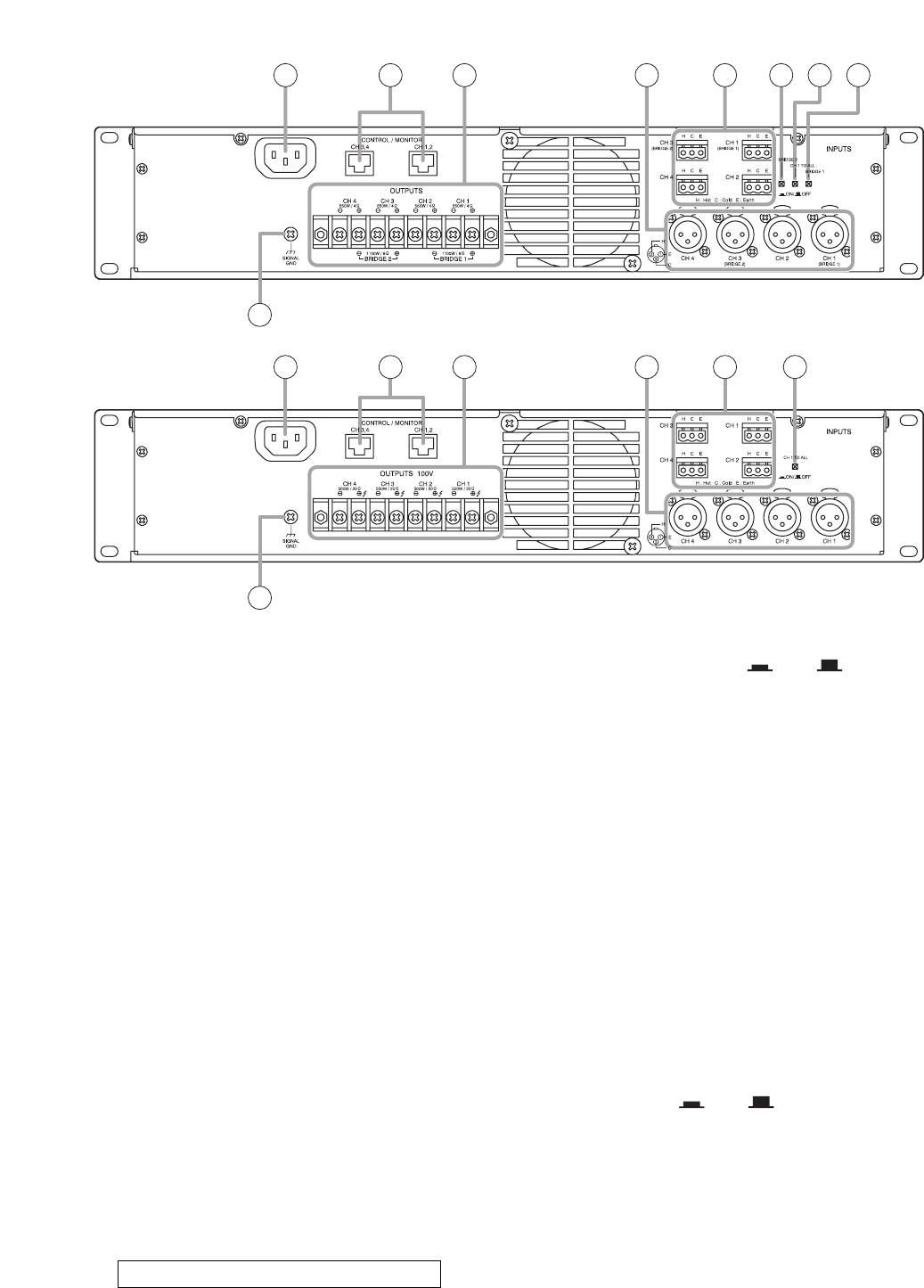
[Rear]
6. AC inlet
Connect the supplied power cord to this inlet.
The socket-outlet shall be installed near the
equipment and the plug (disconnecting device)
shall be easily accessible.
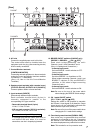
7. Control/Monitor terminals
[CONTROL/MONITOR]
Connecting external equipment to these terminals
makes the control and monitor functions available
for channels 1 – 4 individually.
(See p.15; How to Use the Control/Monitor
Terminals.)
8.
Speaker output terminals (with a terminal cover)
[OUTPUTS (DA-550F), OUTPUTS 100 V (DA-500FH)]
Connect speaker cables to these terminals.
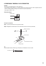
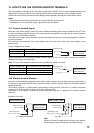
9. Input terminals [INPUTS]
Electronically-balanced input terminals.
Each removable terminal block (3 pins) is
internally connected in parallel to the
corresponding XLR type connector.
• Removable terminal block (3 pins)
H: Hot, C: Cold, E: Earth
•
XLR type male connector (XLR-3-31 equivalent)
Pin 1: Earth, Pin 2: Hot, Pin 3: Cold
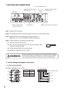
If a straight plug hits the rack's rear cover or
wall behind the rack when it is used for
connection, use the L-shaped plug instead.
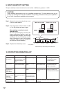
10. BRIDGE ON/OFF switches (DA-550F only)
[BRIDGE 1, BRIDGE 2, ON / OFF]
Used when bridge-connecting the unit's
Channels 1 and 2, and Channels 3 and 4.
(See p. 8; Settings and Connections.)
• 4-channel input mode
Set both BRIDGE 1 and 2 switches to OFF.
(factory-preset)
• 3-channel input mode
Set either BRIDGE 1 or 2 switches to ON.
When bridge-connecting Channels 1 and 2, set
BRIDGE 1 switches to ON, and BRIDGE 2
switches to ON when bridge-connecting
Channels 3 and 4.
• 2-channel input mode
Set both BRIDGE 1 and 2 switches to ON.
Note: Be sure to first turn off the power switch
when changing the BRIDGE switch settings.
11. CH 1 mode ON/OFF switch
[CH 1 TO ALL, ON / OFF]
Setting this switch to ON (pressed in) transmits
the Channel 1 input signal to all channels. Output
signal levels can be individually adjusted with
each channel's input level control (3).
Note: Be sure to first turn off the power switch when
changing the CH 1 mode switch settings.
12. Functional ground terminal [SIGNAL GND]
Hum noise may be generated when external
equipment is connected to the unit. Connecting
this terminal to the functional ground terminal of
the external equipment may reduce the hum noise.
Note: This terminal is not for protective earth.
Caution when using an XLR type plug