5
9 10
21 22
11 12 13 14 15 16
18
19
17
20
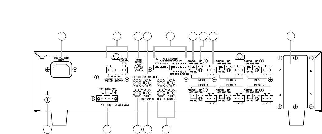
[Rear]
9. AC inlet
Connect the supplied power cord.
10. Remote control connector
Removable terminal block.
(1) Remote volume control terminals
[REMOTE VOLUME]
Connecting a 10 kΩ linear taper volume control
across these terminals will allow remote control
of preamplifier output and speaker output levels.
(2) Power remote control terminals
[POWER REMOTE]
Allows remote control of the unit's power
ON/OFF.
No-voltage make contact input.
(3) Mute control terminals [MUTE CONTROL]
Shorting these terminals mutes the Mute
Receive inputs (the inputs set to be muted).
The mute control works regardless of whether or
not there is a signal to a Mute Send input (the
input set to activate muting).
11. Mute sensitivity control [MUTE SENSE]
Adjusts the threshold level in a range of 36 dB
for the Mute Send inputs to activate the mute
function. Turn clockwise to increase the
threshold level (lower sensitivity), and
counterclockwise to decrease the level (higher
sensitivity).
12. Preamplifier output jack [PRE AMP OUT]
0 dB, 600 Ω, unbalanced RCA jack. Outputs all
input signals. Connects to a signal processor
such as a limiter or equalizer. (Refer to p. 7.)
13. Mute assignment switches
[MUTE ASSIGNMENT]
Assign the individual inputs to Mute Receive
(inputs to be muted) or Mute Send (inputs to
activate muting) function. When a signal enters a
Mute Send input, Mute Receive inputs are all
muted.
Note
Avoid assigning both functions to the same input.
(1) Mute Receive assignment switches
[MUTE RECEIVE (INPUT CH)]
Allow all inputs (INPUT 1 – 8 and Module) to be
assigned to Mute Receive function.
(2) Mute Send assignment switches
[MUTE SEND (INPUT CH)]
Allow the inputs 1 – 3 and Module input to be
assigned to Mute Send function.
14. Function switches
(1) Phantom power ON/OFF switch
[PHANTOM ON, OFF]
Turns on or off the phantom power for the
corresponding input. This switch is valid only
when the LINE/MIC selector switch is set to the
MIC position.
(2) LINE/MIC selector switch [LINE, MIC]
Selects the input sensitivity of LINE or MIC as
follows:
LINE: –10 dB
MIC: –70 to –50 dB, adjustable with the
Microphone gain trimmer (15).
15. Microphone gain trims [MIC TRIM]
Adjust the microphone input gain for the inputs
set to MIC.
16. Input 1 – 6 connectors [INPUT 1 – 6]
–10 dB (LINE) or –70 to –50 dB (MIC)
selectable, 600 Ω, balanced, removable terminal
blocks.
Either LINE or MIC level can be selected by the
Function switch (14).
When MIC level is selected, the input sensitivity
can be adjusted from –70 to –50 dB with the
Microphone gain trim (15).
The inputs 2 and 3, which are electronically
balanced, can be converted into transformer-
balanced type by using optional transformers IT-
455.
This figure represents the A-724.


