


LFE Level
Rear Wall Distance
Side Wall Distance
LFE Input
LFE Output
Normal Input
Normal Output
Trigger OnFuse
Auto
On
WARNING
TO PREVENT FIRE OR SHOCK HAZARD
DO NOT EXPOSE THIS UNIT TO RAIN OR MOISTURE
NO USER SERVICEABLE PARTS INSIDE
REFER SERVICING TO QUALIFIED PERSONNEL
REPLACE FUSE ONLY WITH SAME RATING
ATTENTION
POUR EVITER TOUS RISQUES DE FEU OU DE CHOC ELECTRIQUE
N'EXPOSEZ PAS CET APPAREIL A L'HUMIDITE
AUCUN COMPOSANT NE PEUT ETRE REMPLACE PAR L'UTILISATEUR
VEULLEZ CONTACTER LE SERVICE APRES VENTE AGREE
REMPLACER LE FUSIBLE PAR UN AUTRE DE LA MEME VALEUR
CAUTION
RISK OF ELECTRIC SHOCK
DO NOT OPEN
AVIS: RISQUE DE CHOC ELECTRIQUE - NE PAS OUVRIR
!
THI E L
SmartSub
®
Patents Pending
Model
Ser N
o
Voltage
THIEL Audio • 1026 Nandino Boulevard • Lexington, Kentucky • USA • www.thielaudio.com
On
120v 8A
240v 4A
Slo-blow
Select
Decrease
Increase
meters
meters
Off
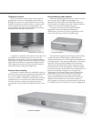
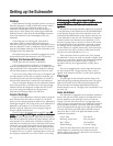
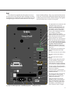
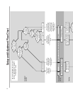
Power cord plugs here Turn power on here
This light and the one on the front of the
subwoofer will glow green if the
amplifier is currently operational, and
red for 5 seconds during start-up or if
the amplifier is set for auto-on that is
not currently activated. It will flash in
various colors and patterns when heat
or line voltage is a problem.
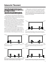
Set this adjustment to match the
distance from the side of the subwoofer
to the side wall of the room (in meters).
Set this adjustment to match the
distance from the rear of the subwoofer
to the rear wall of the room (in meters).
This level adjustment functions only for
the LFE input. If you are not using the
LFE input, set this to minimum
(OFF). If the subwoofer volume is set
by the processor then a good starting
point is 90.
This displays the current setting of the
adjustment designated by the light
above.
This button increases the active setting.
This button selects which setting is
active.
This button decreases the active
setting.
Connect an input cable to this connec-
tor if the subwoofer is being used for
the processor’s subwoofer output.
If the LFE input is used, this connector
can connect to an additional subwoofer.
Connect an input cable to this connec-
tor if the subwoofer is being driven by a
crossover or Integrator.
If the Normal input is used, then this
connector can be used to connect to an
additional subwoofer.
DC voltage (5-25 volts) to this jack will
turn the amplifier on if the auto/on
switch is set to auto. Removing the
voltage turns the amp off.
Setting this switch to On turns the
amplifier on (after a 3 second start-up
delay) provided that the main power
switch is on. The Auto position allows
the amplifier to automatically turn on
when it detects an input or a trigger.
11
See page 14 for fuse replacement
Feet
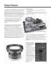
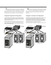
The subwoofer is supplied with four pointed, screw-in
feet that can be used to provide firmer coupling to the floor
for slightly better sound quality and to prevent the unit from
moving during use. Please be advised that their use can put
dents in hardwood floors. They are screwed into the bottom
of the unit, and should be individually adjusted until the unit
is firmly seated onto the floor without rocking. Then tighten
each of the back-nuts to lock the feet in place.