


Quick Start List for Platform
2-5
Quick Start
- Evaluation Module Preparations
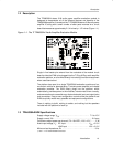
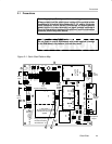
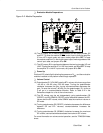
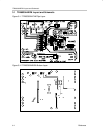
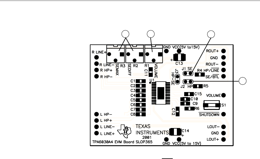
Figure 2–2. Module Preparation
11
10
1213
10) The SE jumper, J1, is used to select between the two output modes, SE
and BTL. To allow the module SE/BTL
control input to force the amplifier
IC into a BTL output mode, set output mode jumper J1 to OFF. To keep
the module amplifier IC in the single-ended output mode regardless of the
control input state, set jumper J1 to ON.
11) The HP jumper, J2, is used to select between the two input modes, HP and
LINE. To keep the amplifier IC in LINE input mode, set J2 to OFF. To keep
the amplifier IC in the HP input mode, set jumper J2 to ON.
- Power Up
Platform LED1 should light indicating the presence of V
CC
, and the evaluation
modules installed on the platform should begin operation.
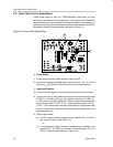
- Volume Control
12) Potentiometer R1 (VOLUME) sets the BTL volume, which can range from
–40 dB to +36 dB using 2.53 dB steps. Turning the potentiometer
clockwise increases the gain; turning counterclockwise decreases the
gain. To mute the volume (–80 dB), turn the poteniometer, R1, as far as
it will go in a counterclockwise direction. Refer to Table 3–2 in the
Reference chapter for a list of the volume levels.
13) The SE volume may be set independently using potentiometers R2
(SEDIFF) and R3 (SEMAX). SEDIFF set the difference between the BTL
volume and the SE volume, while SEMAX sets the maximum volume in
SE mode.
14) Turning potentiometer R2 (SEDIFF) clockwise decreases the difference
between SE and BTL volumes; counterclockwise increases the
difference.
15) Turning potentiometer R3 (SEMAX) clockwise increases the maximum
SE volume; counterclockwise decreases the maximum SE volume.
For more information on volume control operation, see the TPA6030A4 data
sheet.