


www.ti.com
0.1 µF
0.1 µF
0.47 µF
33 µH
33 µH
OUTP
OUTN
L
1
L
2
C
1
C
2
C
3
1 nF
Ferrite
Chip Bead
OUTP
OUTN
Ferrite
Chip Bead
1 nF
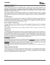
GainsettingviaGAIN0andGAIN1inputs
INPUTRESISTANCE
TPA3008D2
SLOS435A–MAY2004–REVISEDJULY2004
APPLICATIONINFORMATION(continued)
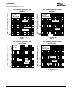
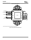
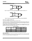
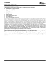
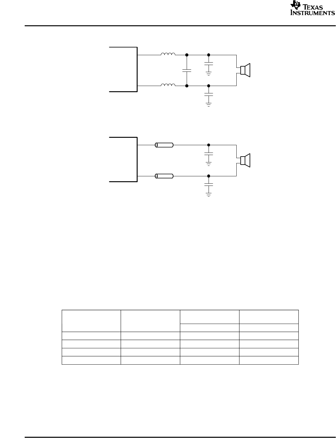
Figure19.TypicalLCOutputFilter,CutoffFrequencyof27kHz,SpeakerImpedance=8Ω
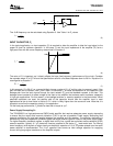
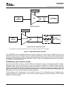
Figure20.TypicalFerriteChipBeadFilter(Chipbeadexample:Fair-Rite2512067007Y3)
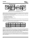
ThegainoftheTPA3008D2issetbytwoinputterminals,GAIN0andGAIN1.
ThegainslistedinTable1arerealizedbychangingthetapsontheinputresistorsinsidetheamplifier.This
causestheinputimpedance(Z
i
)tobedependentonthegainsetting.Theactualgainsettingsarecontrolledby
ratiosofresistors,sothegainvariationfrompart-to-partissmall.However,theinputimpedancemayshiftby
20%duetoshiftsintheactualresistanceoftheinputresistors.
Fordesignpurposes,theinputnetwork(discussedinthenextsection)shouldbedesignedassuminganinput
impedanceof26kΩ,whichistheabsoluteminimuminputimpedanceoftheTPA3008D2.Atthelowergain
settings,theinputimpedancecouldincreaseashighas165kΩ
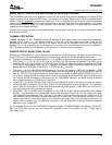
Table1.GainSetting
INPUTIMPEDANCE
AMPLIFIERGAIN(dB)
(kΩ)
GAIN1GAIN0
TYPTYP
0015.3137
0121.288
1027.252
1131.833
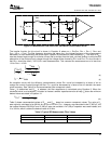
Eachgainsettingisachievedbyvaryingtheinputresistanceoftheamplifierthatcanrangefromitssmallest
value,33kΩ,tothelargestvalue,137kΩ.Asaresult,ifasinglecapacitorisusedintheinputhigh-passfilter,
the-3dBorcutofffrequencychangeswhenchanginggainsteps.
16