


2-4
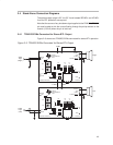
2.3 Quick Start List for Stand-Alone
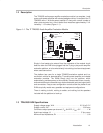
Follow these steps to use the TPA0253 EVM stand-alone or when connecting
it into existing circuits or equipment. Connections to the TPA0253 module
header pins can be made via individual sockets, wire-wrapping, or soldering
to the pins, either on the top or the bottom of the module circuit board.
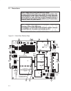
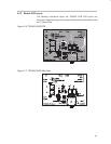
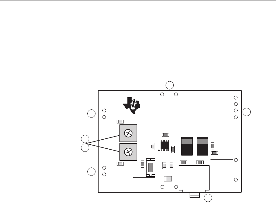
Numbered callouts for selected steps appear in Figure 2–2.
Figure 2–2. Module Map
2
4
4
5
5
6
8
GND
LO/MO+
SHUTDOWN
GND
C3
VDD GND
GND
LIN
VDD GND
GND
RIN
TPA0253 EVM Board
U1
+
TEXAS
INSTRUMENTS
2000
R2
S1
R1
STEREO/MONO
C4
C5
R4
C6
C1
C2
J1
R3
R5
SLOP270
SHUTDOWN
R9 R6
C8 C7
R8
R7
+
RO/MO+
- Power supply
1) Ensure that all external power sources are set to
OFF.
2) Connect an external regulated power supply set to 5 V to the module VDD
and GND pins taking care to observe marked polarity.
- Inputs and outputs
3) Ensure that audio signal source level adjustments are set to minimum.
4) Connect the right (left) positive lead of the audio source to the module RIN
(LIN) pins and the negative lead to the GND pin.
5) Connect a speaker to the module RO/MO+ and LO/MO– pins
OR
plug a
headphone into to EVM headphone jack J1.
- Evaluation module preparations
6) Adjust EVM potentiometers R2 and R4 to approximately mid point.
- Power-up
7) Verify correct voltage and input polarity and set the external power supply
to
ON.
The EVM should begin operation.
8) Adjust the signal source level or adjust potentiometers R2 and R4 on the
EVM as needed.