TMS320F2809, TMS320F2808, TMS320F2806
TMS320F2802, TMS320F2801, TMS320C2802
TMS320C2801, TMS320F28016, TMS320F28015
www.ti.com
SPRS230L–OCTOBER 2003–REVISED DECEMBER 2009
Digital Signal Processors
Check for
Samples: TMS320F2809, TMS320F2808, TMS320F2806, TMS320F2802, TMS320F2801, TMS320C2802, TMS320C2801, TMS320F28016,
TMS320F28015
1 F280x, F2801x, C280x DSPs
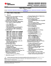
1.1 Features
1234
– Prevents Firmware Reverse Engineering
• High-Performance Static CMOS Technology
• Three 32-Bit CPU Timers
– 100 MHz (10-ns Cycle Time)
• Enhanced Control Peripherals
– 60 MHz (16.67-ns Cycle Time)
– Up to 16 PWM Outputs
– Low-Power (1.8-V Core, 3.3-V I/O) Design
– Up to 6 HRPWM Outputs With 150 ps MEP
• JTAG Boundary Scan Support
(1)
Resolution
• High-Performance 32-Bit CPU (TMS320C28x)
– Up to Four Capture Inputs
– 16 x 16 and 32 x 32 MAC Operations
– Up to Two Quadrature Encoder Interfaces
– 16 x 16 Dual MAC
– Up to Six 32-bit/Six 16-bit Timers
– Harvard Bus Architecture
• Serial Port Peripherals
– Atomic Operations
– Up to 4 SPI Modules
– Fast Interrupt Response and Processing
– Up to 2 SCI (UART) Modules
– Unified Memory Programming Model
– Up to 2 CAN Modules
– Code-Efficient (in C/C++ and Assembly)
– One Inter-Integrated-Circuit (I2C) Bus
• On-Chip Memory
• 12-Bit ADC, 16 Channels
– F2809: 128K x 16 Flash, 18K x 16 SARAM
– 2 x 8 Channel Input Multiplexer
F2808: 64K x 16 Flash, 18K x 16 SARAM
F2806: 32K x 16 Flash, 10K x 16 SARAM – Two Sample-and-Hold
F2802: 32K x 16 Flash, 6K x 16 SARAM
– Single/Simultaneous Conversions
F2801: 16K x 16 Flash, 6K x 16 SARAM
– Fast Conversion Rate:
F2801x: 16K x 16 Flash, 6K x 16 SARAM
80 ns - 12.5 MSPS (F2809 only)
– 1K x 16 OTP ROM (Flash Devices Only)
160 ns - 6.25 MSPS (280x)
– C2802: 32K x 16 ROM, 6K x 16 SARAM 267 ns - 3.75 MSPS (F2801x)
C2801: 16K x 16 ROM, 6K x 16 SARAM
– Internal or External Reference
• Boot ROM (4K x 16)
• Up to 35 Individually Programmable,
– With Software Boot Modes (via SCI, SPI, Multiplexed GPIO Pins With Input Filtering
CAN, I2C, and Parallel I/O)
• Advanced Emulation Features
– Standard Math Tables
– Analysis and Breakpoint Functions
• Clock and System Control
– Real-Time Debug via Hardware
– Dynamic PLL Ratio Changes Supported
• Development Support Includes
– On-Chip Oscillator
– ANSI C/C++ Compiler/Assembler/Linker
– Watchdog Timer Module
– Code Composer Studio™ IDE
• Any GPIO A Pin Can Be Connected to One of
– DSP/BIOS™
the Three External Core Interrupts
– Digital Motor Control and Digital Power
• Peripheral Interrupt Expansion (PIE) Block That
Software Libraries
Supports All 43 Peripheral Interrupts
• Low-Power Modes and Power Savings
• 128-Bit Security Key/Lock
– IDLE, STANDBY, HALT Modes Supported
– Protects Flash/OTP/L0/L1 Blocks
– Disable Individual Peripheral Clocks
(1) IEEE Standard 1149.1-1990 Standard Test Access Port and
Boundary Scan Architecture
1
Please be aware that an important notice concerning availability, standard warranty, and use in critical applications of Texas
Instruments semiconductor products and disclaimers thereto appears at the end of this data sheet.
2Code Composer Studio, DSP/BIOS, MicroStar BGA, TMS320C28x, C28x, TMS320C2000 are trademarks of Texas Instruments.
3eZdsp is a trademark of Spectrum Digital.
4All other trademarks are the property of their respective owners.
PRODUCTION DATA information is current as of publication date.
Copyright © 2003–2009, Texas Instruments Incorporated
Products conform to specifications per the terms of the Texas
Instruments standard warranty. Production processing does not
necessarily include testing of all parameters.


