


The TPA311 MSOP Audio Power Amplifier Evaluation Module
3-5
Details
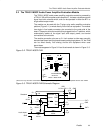
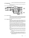
3.2.3 SIngle-Ended Operation
For single-ended operation, the module SE/BTL control input pin must be held
high. The speaker (or headphone) load is connected to the module OUT+
output pin through a coupling capacitor, and to platform/system ground. A
470-µF electrolytic coupling capacitor is provided on the platform in the signal
path to the headphone output jack for this purpose and a control signal from
the platform headphone jack can be routed to the module control input pin to
switch the TPA311 IC to the single-ended mode.
In the single-ended mode, the amplifier inside the TPA311 IC that drives the
OUT– line does not operate and does not dissipate any power. The OUT– pin
goes into a high-impedance state and can be left connected or allowed to float.
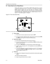
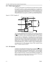
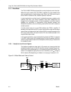
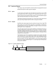
3.2.4 Module Gain
The TPA311 MSOP evaluation module has a set gain of 2. However, the gain
can be adjusted to a maximum of 22 by changing the value of resistor R3
(Figure 3–3). Use the following equation to determine value of R
3:
Gain
–R
3
R
2
The TPA311 amplifier IC, as most other amplifiers, exhibits its best distortion
and noise performance at lower gain levels (see the TPA311 data sheet). Even
so, the TPA311 at its highest gain setting has significantly less distortion than
most low-cost speakers.
Gain versus total harmonic distortion (THD) should be considered in each
application. Both the module input signal level and the TPA311 MSOP module
gain should be adjusted to obtain the lowest overall distortion level for a
particular overall gain. A quick rule of thumb (everything else being equal): the
module input signal level should be as high as possible without clipping or
overloading the TPA311 input, and the TPA311 gain should be kept as low as
possible.
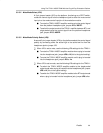
3.2.5 Shutdown
When the shutdown terminal of the TPA311 amplifier IC is taken high, the IC
ceases operation and enters an ultralow-power state. This is accomplished by
applying a control signal to the module shutdown pin or by pressing the shut-
down switch, S1, on the module. When the control signal goes low or is re-
moved (or the switch is released), amplifier operation resumes.
The plug-n-play platform can generate the shutdown (mute) signal for the
module either when a plug is inserted into the platform headphone output jack
or when the plug is removed, as selected by a platform jumper (JP8).