


2
0
3
0
4
0
5
0
6
0
9
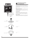
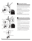
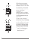
DIRECTV Multi-Satellite Dish Antenna
Hooking up cables (one shown) to the LNB and attaching the LNB
to Antenna — up to four cables can be connected this way.
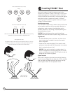
Pencil Marks
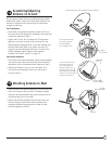
Attaching LNB to Antenna
The triple-head LNB has four identical outputs, each
supporting one independently operating receiver. To simplify
future installation of additional receiver(s), you may want to
route more cables to the antenna at this point. Only one cable
is needed for antenna fine-tuning and alignment.
•
RG 6 cable from the grounding block can now be routed to
the LNB on your antenna. Attach the triple-head LNB onto
the LNB Arm and fasten with included mounting hardware
(Philip screws and nuts). Dress cable with enclosed tie
wraps, allowing for cable water drip loop if necessary.
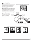
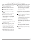
Aiming and
Fine-tuning Antenna
When you fine-tune the antenna to one satellite, the other two
satellites should be aligned automatically. Plug in and turn on
your receiver.
•
Use the on-screen signal strength meter to fine-tune the
antenna. It is important to obtain the strongest signal
possible; the higher the signal strength, the less likely you
are to experience signal outages during adverse weather.
•
With a cell phone and house phone, ask someone to relay
signal strength values to you, or hook-up a portable TV at the
installation site. Your receiver may be equipped with an
audible beep tone feature; the higher pitch, the higher the
signal. A hand-held signal meter is also an option.
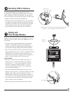
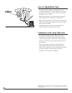
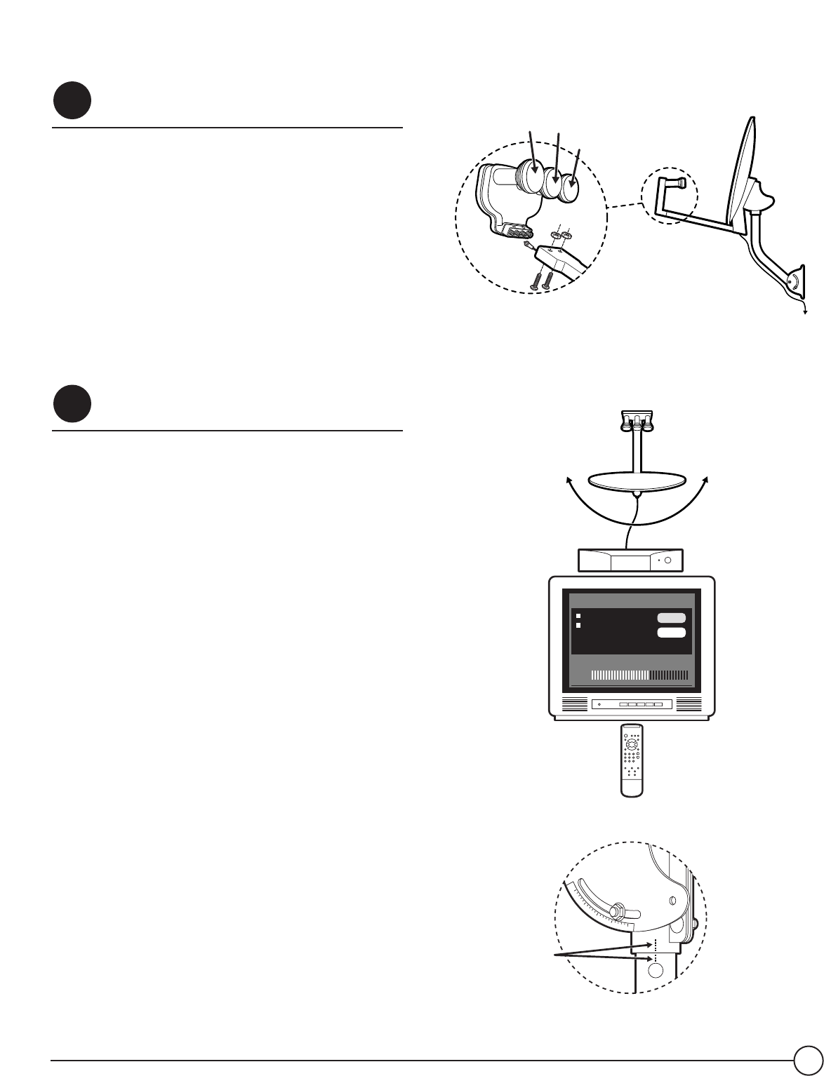
Align the Azimuth
•
Set your on-screen menu to the signal meter mode, on
Satellite A (101°). Use a transponder that is unique to
Sat A (such as 1 - 6, 16) for your alignment. Point the
antenna to a generally southerly direction, or use the
Azimuth number obtained in Step 1 and a compass for
a more precise starting point.
•
Very slowly rotating the antenna around the mast a few
degrees at a time, pause 3 - 5 seconds in between for signal
strength meter update. You should be able to find the
satellite signal first and then the signal peak, indicated on
your screen. Once you sweep through the peak-signal point
on the screen, stop. You may want to swing past the peak
point a couple of times to make sure.
•
Mark the mast and antenna bracket point with a pencil.
STEP
9
STEP
8
Sat B,
119°
Sat C,
110°
Sat A,
101°
Antenna
Transponder: 23, Sat B
Antenna Location:
Azimuth: 152
Elevation: 50
Tilt: 102
Clear
OK
Current Level: 0 Peak Level: 75
Signal:
Align the
Azimuth