


IP-223 to Kenwood Radios 1
1 General
The application note is intended to show how to assemble the cable and setup the hardware of
the IP223 for channel change and FleetSync applications using Kenwood radio.
2 Setup
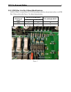
2.1 TK-x150/180 Model Cable Assembly:
NOTE: There are differences between the TK-x150 and TK-x180 radios DB25 connectors.
If COR is used, pin 20 (TK-x150 an output only) will be programmed for that function and
the cable will route that signal to the IP-223. On the TK-x180 the same pin is a general
purpose I/O and has an additional 470 ohm series resistance added. This requires that the IP-
223 external pull-up resistance must be removed. Jumpers J8 (Line 1) and J30 (Line 2)
should be placed in a neutral position (neither A or B, hanging).
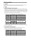
The tables below show the assembly cable for the TK-x150 model radios.
Signal IP223 DB25 TK-x150 Radio DB25
Ground
7 7
PTT Common
2 7
PTT
14 12 (Aux Input 4 Programmable)
COR
20 20 (Aux Output 1 Programmable)
RX+
24 17
TX+
25 6
IP223 DB9
IP223 Serial
Signal
Line 1 Line 2
TK-x150 Radio DB25
TXD
2 8 2
RXD
3 7 3
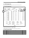
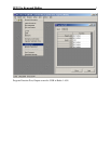
For IP223 Rev F board or later make sure jumper J35 is in “A” position for line 1 and jumper
J26 is in “A” position for line 2.
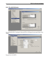
2.2 TK-x80 Model Cable Assembly:
The KCT-19 accessory cable from Kenwood radio is needed and the 'E' connector is
connected to CN4 inside the radio to establish the serial communication.
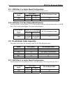
The tables below show the assembly cable for the TK-x80 model radios.
Signal IP223 DB25 KCT-19 Accessory Conn.
Ground
7 6
PTT Common
2 6
PTT
14 8
COR
20 11
RX+
24 12
TX+
25 5