


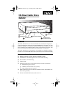
Rear Panel
TEAC CD-RW Installation Guide 3
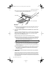
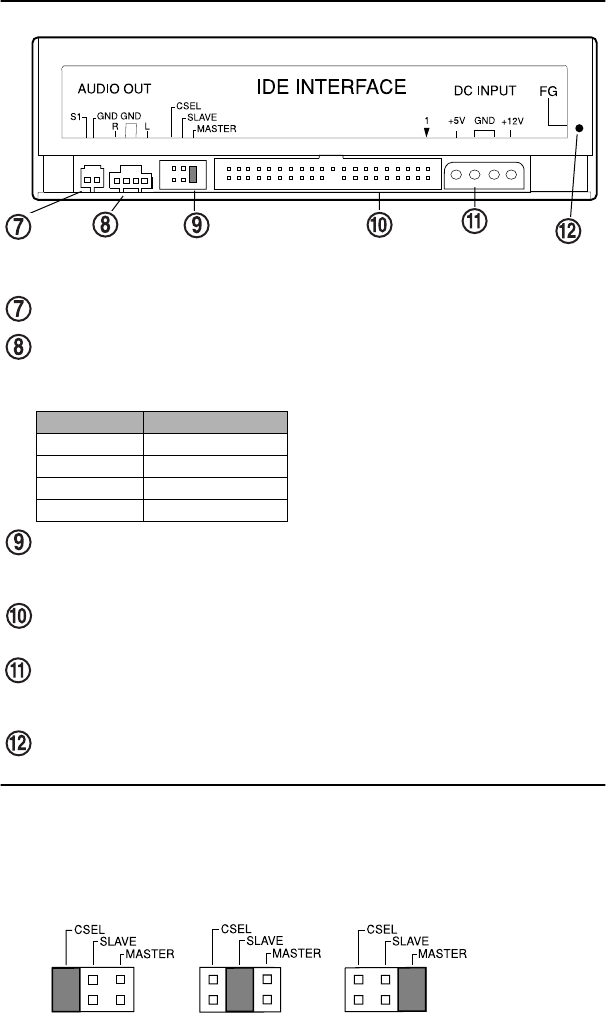
Rear Panel
S1:
Reserved for factory use only.
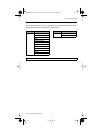
analog audio output connector:
You can use an audio cable to connect this
connector to the audio input connector on a sound card. Pin assignments are
described below:
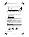
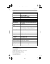
CSEL/Slave/Master configuration jumper:
The CD-RW Drive includes three
pairs of jumper pins on the rear panel that allow you to set the drive to CSEL,
Slave, or Master mode.
interface connector:
Use an IDE interface ribbon cable to connect the CD-RW
drive to an IDE interface in your computer.
power connector:
Connect the power connector to the +5VDC and +12VDC
power sources. The +5VDC terminal is on the left as you face the rear panel; the
+12VDC terminal is on the right. The two center terminals are ground terminals.
FG:
Frame ground. This is a ground connection for the CD-RW Drive.
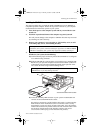
Configuring the CD-RW Drive
The Master/Slave/CSEL jumper configuration of your TEAC CD-RW drive will
depend on whether or not you have an IDE CD-ROM/DVD drive installed in your
system. The following section will guide you through most typical system
configurations.
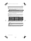
Pin Number Audio Signal
1 Left signal
2 Ground
3 Ground
4 Right signal
CSEL/Slave/Master interface
connector
power
connector
frame
ground
configuration jumper
analog audio
connector
S1
jumper
jumper
jumper
set to CSEL
set to Slave
set to Master (default)
CDRW8x8x32short.fm Page 3 Thursday, October 19, 2000 9:58 PM