


4
TASCAM IF-AE8
IF-AE8 Digital Audio Converter
The TASCAM IF-AE8 provides a convenient way of
exchanging digital audio data between
TDIF-1-equipped devices, such as DTRS recorders,
and AES/EBU devices.
A single TDIF-1 connector carries eight channels of
digital input and output. Four XLR-type connectors
accept four two-channel input signals in AES3-1992
format, and another four XLR-type connectors out-
put four two-channel input signals in AES3-1992
format.
The word synchronization is selectable, using a front
panel switch, from any of the four
AES/EBU
inputs,
from the TDIF-1 source, or from an external inde-
pendent word clock source.
The word clock source can be used as the clock
source for sampling frequency conversion. All stan-
dard rates (32 kHz, 44.1 kHz and 48 kHz) are sup-
ported for input and output.
If sampling frequency conversion is carried out, the
IF-AE8 will generate an independent clock signal,
based on the target frequency, so that other units may
be synchronized to it.
The signal transmitted from the
AES/EBU
outputs
can be selected to come from the
AES/EBU
input
signals or from those received at the TDIF-1 connec-
tor, using a front panel switch.
Format conversion is possible with up to 24-bit data
with TDIF digital audio format, and 20-bit with
AES3-1992 format data if no sample rate conversion
is performed (20-bit data for both formats if the sam-
pling frequency is converted).
The digital audio output format is selectable as either
professional or consumer format using a front panel
switch.
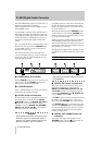
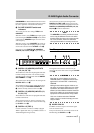
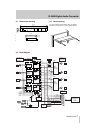
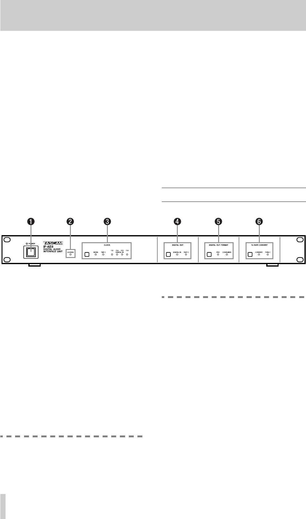
1 Front panel
1
POWER switch and indicator
Push the
POWER
switch once to turn on power, and
again to turn it off. The
POWER
indicator lights
when power is supplied to the IF-AE8.
2
LOCKED indicator
When a valid clock signal is received at the selected
clock source, this indicator will light.
3
CLOCK switch and indicators
This switch allows you to cycle between the six pos-
sible clock sources for the IF-AE8: the
WORD
SYNC IN
A
connector, the
DIGITAL I/O (TDIF-1)
9
connector, or any of the four two-channel
AES/EBU connectors (
DIGITAL I/O (AES/EBU)
INPUTS (1/2, 3/4, 5/6, 7/8)
8
), as shown by the
indicators to the right of the switch.
WARNING
There should usually never be more than one
word clock signal in a digital audio system. If
there are not, at worst, damage may occur to
speakers, amplifiers, etc. as a result of
high-frequency noise generated by word clock
incompatibilities.
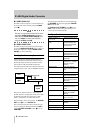
4
DIGITAL OUT switch and indicators
This switch allows you to select the source of the
digital audio signals that are output from the
DIGITAL I/O (AES/EBU) OUTPUTS (1/2, 3/4,
5/6, 7/8)
7
. The source can either be the signals
received at the
AES/EBU
inputs
8
(
DIGITAL IN
)
or at the
TDIF-1
connector
9
.
If the
TDIF-1
option is selected, the eight channels of
the TDIF-1 audio are mapped on a “one-to-one”
basis to the eight
AES/EBU
audio output channels.
If the
DIGITAL IN
option is selected, the input data
received at the
AES/EBU
ports is passed through to
the corresponding output ports. However, it may be
passed through the sample rate conversion before
reaching the output ports.
5
DIGITAL OUT FORMAT switch and
indicators
The format of the digital audio output from the
AES/EBU
output connectors
7
may be either pro-
fessional AES3-1992 format (
PRO
) or