


5
1. Introduction
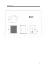
Thank you for purchasing Tannoy B225.
The Tannoy B225 is a 15” direct radiating bass loudspeaker system. For installations
that require extended bass response from an ultra-compact cabinet, with flying and
wall-bracket mount capabilities, the B225 makes the ideal companion to Tannoys' i/T
series of sound reinforcement loudspeakers.
The B225 uses a high efficiency 15” driver, combining powerful, natural bass
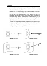
performance with compact dimensions. M10 flying points located around the cabinet
mean the B225 can be quickly and easily installed using the EBS10 Eye Bolt Set.
Capable of delivering high sound pressure levels with extremely low distortion, the
B225 adds extra low frequencies with traditional Tannoy reliability.
2. Unpacking
Every Tannoy B225 product is carefully inspected before packing. After unpacking
your loudspeakers, please inspect for any exterior physical damage, and save the
carton and any relevant packaging materials in case the loudspeaker again requires
packing and shipping. In the event that damage has been sustained in transit notify
your dealer immediately.
3. Connectors/Cabling
The B225 is fitted with two 4-pole Speakon™ connectors. Speakon™ has the
following advantages over EP and XLR type connectors: All terminations are
solderless, this makes life easier at the time of installation or when field servicing is
required. Contacts will accept 6 sq. mm wire with an outside diameter of up to 15 mm
and a current rating of 30 Amps.
The pins of the two Speakon™ sockets, marked input/output on the rear of the input
panel, are paralleled within the enclosure.
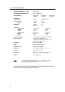
Tannoy have adopted the following wiring standard for B225:-
SPEAKON™
CONNECTOR
SIGNAL
Pin 1+ Positive
Pin 1- Negative
Should you encounter any problems obtaining Speakon™ connectors, please contact
Neutrik or its distributors on the following numbers:-
UK: NEUTRIK MARKETING: 01983 811 441
USA: NEUTRIK USA INC.: +1 732 901 9488
For a worldwide list of distributors, please contact Neutrik directly on:-
NEUTRIK AG: +423 237 2424
or visit their website at: http://www.neutrik.com/
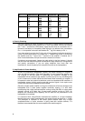
Cable choice consists mainly of selecting the correct cross sectional area in relation to
the cable length and the load impedance. A small cross sectional area would increase
the cables series resistance, inducing power loss and response variations (damping
factor).
Connectors should be wired with a minimum of 2.5 sq. mm (12 gauge) cable. This will
be perfectly satisfactory under normal conditions. In the case of very long cable runs
the wire size should exceed this, refer to the following table for guidance:-