


VOIP-RF-900 Installation Instructions
VI. LED Display Legend
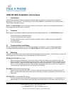
The “master” radio has an array of LEDs that provide various status indicators. Table 2 provides a legend or key
for these various indicators. In order to gain access to the LED array, you will need to open the NEMA box cover
on the “master” radio.
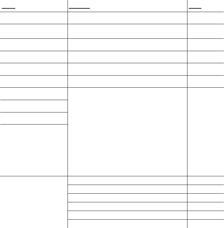
Table 2. VOIP-RF-900 LED Display Legend.
Name
Function
Color
Power
Unit has power and has successfully booted
RED
RF Link
The radio has successfully synchronized with its
matched partner radio
GREEN
RF TX
Radio transmission is occurring
GREEN
RF RX
Radio reception is occurring
GREEN
Eth Link
The Ethernet port has a valid Ethernet connection
GREEN
Activity
The VOIP-RF-900 is processing data
GREEN
1 (channel)
2 (channel)
4 (channel)
8 (channel)
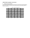
Adding the numbers that are lit will determine the
current radio channel.
1 = 903.12500 MHz
2 = 905.20833 MHz
3 = 907.29167 MHz
4 = 909.37500 MHz
5 = 911.45833 MHz
6 = 913.54167 MHz
7 = 915.62500 MHz
8 = 917.70833 MHz
9 = 919.79167 MHz
10 = 921.87500 MHz
11 = 923.95833 MHz
12 = 926.04167 Mhz
GREEN
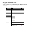
Excellent link quality – no retransmissions
GREEN
Very good link quality – few retransmissions
GREEN
Good link quality – occasional retransmissions
YELLOW
Fair link quality – some retransmissions
YELLOW
Poor link quality – many retransmissions
RED
Link Quality Meter (the more
LEDs that are lit, the higher
the link quality)
No link quality – no link available
RED