


3
NOTE: These instructions apply in the United
Kingdom only – consult your dealer about wiring
conventions in other countries.
Green and yellow wire connects to EARTH (E or
symbol )
Blue wire connects to NEUTRAL (N)
Brown wire connects to LIVE (L)
Please ensure that the replacement lead contains a
5A fuse.
OPTIONAL DC POWER CONNECTIONS
If you have opted for one of our external Whirlwind
DC power supplies this should be connected using
only the cables supplied with the Whirlwind. We
strongly recommend that you do not replace or
attempt to modify these cables. Doing so can
adversely affect the CD player’s performance and is
likely to cause damage.
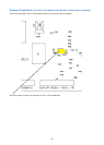
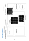
You will also need to re-configure your player for
external DC operation using the internal jumpers as
described below.
Before attempting to re-configure your player, dis-
connect the mains lead at the wall socket. Having
made your player safe, remove the cover by un-
screwing the screws located on the top and those
on the underside using a combination of a T10
security torx driver and a No.1 posi-drive screwdriver
lift the cover and locate the blue jumpers in the back
right corner using Diagram 3 (see page 9) and
position them for the desired configuration. Replace
the cover, connect your Whirlwind power supply and
re-connect the mains lead to the wall socket.
SWITCHING YOUR CD PLAYER ON AND OFF
If you are using a Whirlwind external DC supply to
power the analogue parts of your CD player we
suggest that this, once connected, is left switched
on all the time. To avoid “switch-on thumps” being
transmitted to your loudspeakers when you switch
on your CD player, we recommend that you always
switch on – or cancel mute on – your amplifier last.
Start by powering source components, such as your
CD player, then power the pre-amplifier. Then switch
on the power amplifier. When you’ve finished
listening, mute or turn off the power amplifier and
then mute your pre-amplifier. Finally, turn off your CD
player and other source components. You may, if
you wish, leave your CD player powered up at all
times: this will enable it to deliver optimum
performance as soon as you begin listening,
however we suggest that you switch off the display
when not required. This requires that a disc is
present in the player at all times.
The power switch mounted on the Thunder’s rear
connects and disconnects the mains supply. When
mains is connected, the display on the facia will
illuminate. If you plan to be away from home for long
periods – when, for example, you are on holiday –
you can use this switch to power down the CD
player completely. For absolute safety, disconnect
the mains lead from the wall socket. We advise that
you do this during thunderstorms to avoid damage
from power line surges.
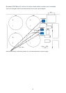
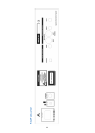
REAR PANEL
Refer to Diagram on Page 11
MAINS CONNECTIONS
Next to the mains switch, on the rear panel, is an
IEC socket into which the supplied mains lead fits.
The fuse in the UK mains plug is a 5A standard type.
Again, if you need to replace it use an identical type
rated at 5A. If the fuses keep blowing return the CD
player to your dealer.
OUTPUT CONNECTIONS
The analogue output sockets on the CD player are
found on the rear panel. There are both balanced
and unbalanced connections available and we
strongly advise you to use the balanced where
possible. Connect these to your amplifier or pre-
amplifier’s CD or Auxiliary input using high quality
interconnect cables (we strongly recommend Merlin
cables for optimum performance). On all players, the
socket marked in red is the right channel, and the
white socket is the left channel.
There are both optical and coaxial digital outputs as
standard on all our players. Our research shows that
the levels of signal jitter caused by separating the
player’s transport mechanism and DAC introduce an
unacceptable degradation in sound quality,
counteracting the benefits accrued through using
our high quality, ultra-low jitter, 24-bit DAC. If you
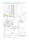
wish to make digital recordings you will need to
switch on the digital output provided using the
yellow internal jumper, see Diagram 1 (see page 7).
However, we caution you that this addition will have
a slight detrimental effect upon the player’s
performance.
Before attempting to re-configure your player, dis-
connect the mains lead at the wall socket. Having
made your player safe, remove the cover by un-
screwing the screws located on the top and those
on the underside using a combination of a T10
security torx driver and a No.1 posi-drive screwdriver
lift the cover and locate the yellow jumper using
Diagram 1 (page 7) and position it for the desired
configuration. Replace the cover and re-connect the
mains lead to the wall socket. The Digital Output
should now work accordingly.