


7
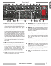
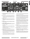
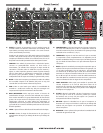
A. INPUTS Plug into either (or both) of the input jacks using a
shielded instrument cable. Press Input Select to choose either
input 1 or 2 to be the active jack as indicated by the LEDs.
The rear panel In jack {LL} can be used instead of input 1 on the
front panel; useful for connecting wireless receivers. NOTE: If
both of these jacks are used at the same time, the front panel
jack overrides the rear panel jack.
• TIP: To overdrive the first tube stage of the preamp, connect
an external preamp inline between your instrument and the
input. For the best pure-tube overdrive sound, boost the out-
put of your external preamp, then dial in a clean Gain setting
using the PreAmp Clip LED {P}. (The Preamp Clip LED does
not monitor the very first preamp tube stage to allow you to
isolate it and overdrive it independent of the Gain controlled
stage of the preamp.)
B. MUTE Press in to disable all output from the unit, except
Tuner Out {KK}; useful when switching or tuning instruments or
during breaks.
C. PAD
Press in to reduce input sensitivity by –10dB; useful for
cleaner response from high-output instruments.
D. BASS INTENSIFIER Press in to engage the Bass Intensifier
circuit as indicated by the LED. The Bass Intensifier boosts
a chosen set of low frequencies combined with a smooth,
fast-acting compressor, providing radical boosts without
overdriving the amplifier; useful for heavier sections of a tune.
Bass Intensifier can also be engaged from the footswitch.
E. LEVEL Adjusts the strength of the Bass Intensifier effect.
F. CUTOFF Limits the frequency range that the Bass Intensifier
operates in from below 80Hz to below 200Hz.
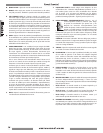
G. COMPRESSION
Press in to engage the Compressor circuit
as indicated by the LED. Compression moderates signal level
as it peaks, according to the way you have controls {H, I, K and
L} set.
H. THRESHOLD
Sets the signal level at which Compression
engages. Turn fully counter-clockwise for maximum sensitivity.
Note that Gain {Q} level and instrument output are what actu-
ally trigger the Compressor.
I. RATIO
Adjusts how much compression is applied once it
has been triggered. For example, at 1:1 there is no compres-
sion. With a ratio of 2:1, an increase of 10 dB will be needed to
increase the output signal level by 5 dB over the threshold. At
10:1, an increase of 10 dB will only increase the output signal
level by 1 dB. (Many consider ratios of 10:1 and greater to be
hard limiting.)
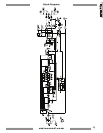
J. COMP POSITION Press to alternate the position of the
Compressor circuit in the signal path from before most of the
tone shaping controls to after, as indicated by the LEDs. See
Block Diagram on page 11.
K. ATTACK Adjusts the rate that Compression engages once
the the signal level rises above the threshold; useful for fine
tuning the transparency of the Compressor effect.
L. RELEASE
Adjusts the rate that Compression disengages
once the signal level drops below the threshold; useful for fine
tuning the transparency of the Compressor effect.
M. METER
Four LEDs indicate the actual amount of gain reduc-
tion in dB.
Front Panel
Input
Select
1
2
-10 dB
Pad
Mute
Preamp
Clip
MIN
MAX
MIN
MAX
Aural
Enhancer
Gain
EQ
Select
1 + 2
1 / 2
MIN
MAX
Level
80
200
Cutoff
-15
+15
Bass
-10
-5
+5
+10
Threshold
Ratio
Position
Comp
MIN
MAX
Attack
MIN
MAX
-2
-8
-18
-4
Release
ON
Power
Footswitch
Volume
Effects
Blend
-15
+15
Treble
Right
Left
Bass Intensifier
PRE EQ
POST EQ
Freq
Level
Equalization 1
Equalization 2
Compression
Boost
S
M
-
1
500
MIN
MAX
1 : 1
2 : 1
10 : 1
20 : 1
120
180
45
35
-15
+15
Mid 1
80 95
Mid 3
650
1k
250
180
-15
+15
Mid 2
450 530
3.4k
5k
1.3k
1k
-15 +15
2.3k 2.8k
120
180
45
35
-15 +15
Mid 1
80
95
3.4k
5k
1.3k
1k
-15
+15
Mid 3
2.3k
2.8k
650
1k
250
180
-15
+15
Mid 2
450
530
MIN
MAX
DRY
WET