


9
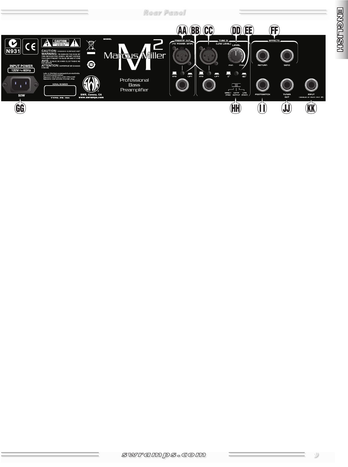
AA.
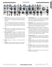
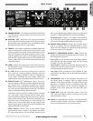
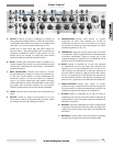
PREAMP OUTPUT— True electronically-balanced XLR and
1/4" TRS jacks for output to Bass Power amp, such as the
SWR Power 750.
BB.
GROUND / LIFT— Disconnects the ground connection
(pin-1) from the Preamp Out and Line Out jacks to reduce
ground loop noise generated from non-standard wiring.
Normally leave this switch out (grounded).
CC.
TUBE DI— Tube driven, transformer coupled outputs suit-
able for connection to studio and “front-of-house” (live)
mixing consoles. These true electronically balanced XLR
and 1/4" TRS jacks are line level outputs in order to maxi-
mize the signal to noise ratio. To avoid clipping (especially
with the XLR output) make sure to set the console input
level to "LINE LEVEL" or reduce the output level using the
Level {DD} control.
DD.
LEVEL— Adjusts the output level of the Line Out jack to
accommodate a variety of sound equipment connections
and input sensitivities.
EE.
0° / 180°— Press to reverse the polarity of the Line Out
jack, useful for reducing phasing problems that may
occur when playing in locations with non-standard wir-
ing or when combining the Line Output signal with
miked cabinet signal. Normally leave this switch out (0°).
FF. EFFECTS LOOP— TRS
1
multipurpose jacks—Send pro-
vides a preamp output and includes onboard tone shap-
ing. Output level is primarily controlled by Gain {Q}.
Effects Return (wet) is mixed with the direct (dry) signal in
any ratio using the Effects Blend control {W}. The Effects
Loop can be bypassed from the footswitch.
The effects loop on the Marcus Miller preamp is located
on a "side chain" circuit, a design used in studio equip-
ment to isolate the effects from the main circuit. This pro-
vides the full sound of your instrument AND allows the
diversity of your external effects to come through. The
effects circuit is also located after the gain stages in the
preamp signal path to bypass the noise associated with
effects inline before the preamp.
t &GGFDUT %FWJDFT Connect Send to your effects device
input and the effect's output to the Return jack. NOTE:
On your effects device—set any wet/dry control fully to
WET to prevent phasing problems and set any input level
control to +4dB (or 0dB if the unit is being overdriven).
t "DDPNQBOJNFOU Connect a CD player, drum machine,
etc. to the Return jack. Adjust accompaniment volume at
the source and with the Effects Blend control {W}.
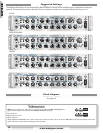
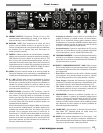
GG.
POWER CORD SOCKET— Connect the included power
cord to a properly wired AC electrical outlet in accor-
dance with the voltage and frequency ratings specified
on the rear panel of your amplifier.
HH. DIRECT / COMPRESSOR OUTPUT / LINE— Choose the
point in the signal path to connect the Line Out jacks. See
Block Diagram on page 48.
t %JSFDU 1SF—A true all-tube signal path taken immedi-
ately after the first tube preamp stage (no EQ). Sounds
most like a Tube D.I. (direct box).
t $PNQ0VUQVU—Depends on the Comp Position switch {I};
always post Gain and Aural Enhancer, but either pre or
post Bass Intensifier and EQ circuits.
t -JOF 1PTU—After all preamp circuits (includes all tone,
compression and effects circuits). Not affected by Master
Volume {X}.
II. FOOTSWITCH— Plug in the (included) footswitch with
any length guitar or speaker cable to enable remote
selection of the Bass Intensifier, EQ Select, Effects Loop
and Boost + Compress mode, as indicated by the LEDs.
Multiple footswitches can be connected together for
multiple access points (stage left and stage right foot-
switches)!
JJ.
TUNER OUT— Plug your instrument tuner in here. This
TRS
1
output can also be used as an always-active, tube-
influenced direct output.
KK.
INPUT— An alternate input to Input 1 on the front panel,
useful for wireless receivers. This input is disabled when a
plug is inserted into Input 1 on the front panel.
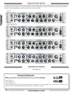
Rear Panel