


User's Manual
8
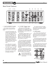
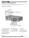
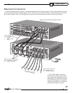
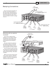
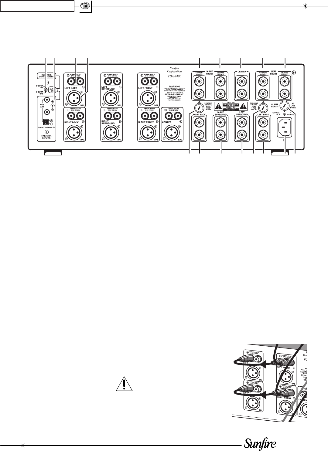
Rear Panel Features
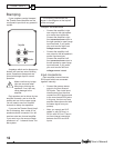
1. AUTO/ON/OFF Switch
Your Theater Grand Amplifi er is
designed with an automatic on/off
circuit.
• In the AUTO-ON po si tion, the
am pli fi er will automatically turn
on if an audio signal is pres-
ent at any of the inputs, or if it
receives a 12 VDC input volt-
age at the trigger inputs. The
amplifi er will automatically turn
off after a few seconds if the
trigger voltage is removed, or
after approximately 30 minutes
in the ab sence of an audio
signal.
• In the ON position, the ampli-
fi er is always on, regardless of
input signals or 12 VDC trigger.
• In the OFF position, the ampli-
fi er is always off, regardless of
input signals or 12 VDC trigger.
• See page 7 for details of the
front panel LED status.
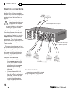
2. 12 VDC Trigger Input
Although the AUTO-ON signal
sensing turn-on is ad e quate for most
installations, the 12 VDC trigger inputs
are offered as an op tion al way to turn
on the amplifi er.
The Sunfi re Theater Grand II, III, IV
and TGP-5 Processors have a com-
pat i ble 12 VDC trigger output (see
page 11). This can be used to auto-
matically turn on the amplifi er when
the processor is turned on.
1/8" mono mini jacks are provided
for ease of installation, along with a
terminal strip to allow more fl exibility
for custom-wired installations. The
terminal strip and both mini jacks are
internally connected in parallel, allow-
ing 'daisy chaining' to turn on multiple
amplifi ers.
Any 1/8" miniplug mono or stereo
interconnect cable will suffi ce to con-
nect the trigger output of the Theater
Grand Processor to the amplifi er.
Do not exceed 18 VDC on
this input. (CAU TION: Do
not connect AC line voltage
to this input!)
The voltage range for the trigger
input is from 5 to 18 VDC. The input
impedance is approximately 600 Ω
(20 mA @ 12V).
3. RCA Inputs
Your Theater Grand Amplifi er has
three sets of inputs for each of the
seven chan nels. Two are un bal anced
RCA in puts and one is a balanced
XLR type.
The two RCA inputs for each chan-
nel are joined together internally, and
either one can be connected to the
cor re spond ing output of your pream-
plifi er.
The second RCA input can be used
as a daisy-chaining output, sending
the pream pli fi er output signal to an-
other channel or to another amplifi er.
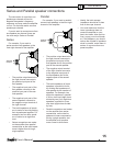
MINIMUM SPEAKER LOAD IMPEDANCE 4 OHMS
CHAPTER 1
5
8
6
9
1
2
34
7
665
66667