


User's Manual
9
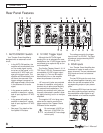
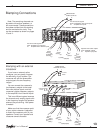
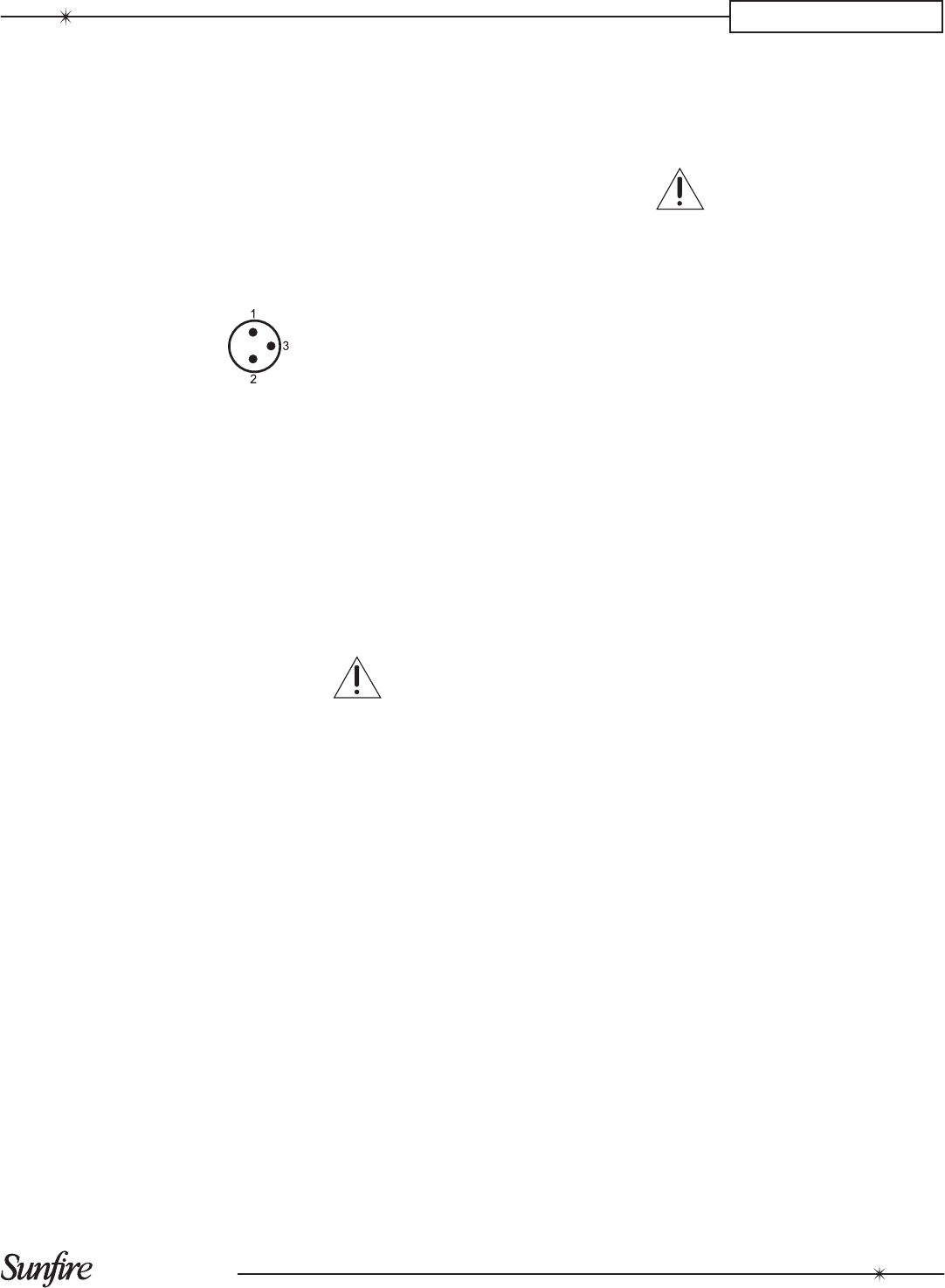
4. XLR Inputs
If your preamplier has XLR
outputs, connect them to these XLR
inputs. These balanced connections
offer superior noise rejection com-
pared to the unbalanced RCA inputs,
particularly for long cable runs.
The female XLR inputs are wired
as follows:
Pin 1 is ground
Pin 2 is positive (hot)
Pin 3 is negative (cold)
Balanced connections pass the
input signal along two conductors. If
there is any external noise and inter-
ference passing into the audio lines,
both conductors will receive the same
amount of noise. This noise is then
rejected in the balanced input stage of
the Theater Grand Amplier.
5. Current Source Outputs
and:
6. Voltage Source Outputs
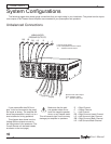
The front left and front right chan-
nels each have a Voltage Source
output and a Current Source output.
The remaining channels have Voltage
Source outputs only.
The Voltage Source outputs have
a source impedance of approximately
zero ohms. The Current Source
outputs have a source impedance of
approximately one ohm.
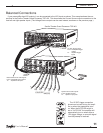
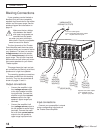
The top post of each binding post
pair is the positive output, and con-
nects to the positive post of your
speaker. The bottom post of each pair
is the negative, and connects to the
negative post of your speaker. The
posts can accept bare wire, spade
terminals, and dual or single banana
connectors.
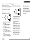
According to your musical taste,
you may select the Current Source for
driving electrostatic, planar magnetic
or ribbon speakers. For cone based
systems, use either. For a biwired sys-
tem, use the Current Source for mid-
range and treble drivers, and use the
Voltage Source for the subwoofer(s).
These are suggestions only. By all
means, please feel free to experiment
with other wiring options. (See page
14.)
NOTE: The Current Source output
is a Voltage Source modied to yield
an impedance of one ohm. This cor-
responds approximately to a vacuum
tube amplier's output impedance and
constitutes the dominant factor in the
soundstage delivery of classic vacuum
tube power ampliers.
7. Current Source Fuses
Each Current Source output has an
in-line fuse to protect your speakers.
If one ever opens, there will be no
output to that speaker.
Unplug the amplier from
the AC mains power supply
if you ever have to change
a fuse.
8. IEC connector
The amplier comes with a detach-
able Linecord which attaches here.
Make sure it is rmly pushed in place.
Connect the other end to an AC outlet
which is properly congured for the
type of plug and has the correct volt-
age for your model.
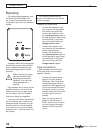
9. Power Switch
Press the top edge of this power
switch to turn the amplier on. The
power LED will turn blue.
The auto/on/off switch (1) controls
how the amplier turns on (signal
sensing, 12V trigger, etc.).
10. AC Line fuse
If this fuse fails, replace it with the
exact same type and current rating.
Note: Always unplug the
power cord from your AC
outlet before removing the
fuse.
Gently turn the fuse carrier counter-
clockwise to release the fuse.
11. LED Dimmer
This switch allows you to set the
brightness of the front panel power
LED, from low, medium and high. Ad-
just this to match the brightness of the
other components in your system.
CHAPTER 1