


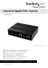


Instruction Manual
2
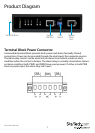
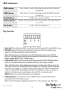
LED Indicators
PWR1 (Green) Solid: Power is connected and active at the PWR1 terminal
connection
PWR2 (Green) Solid: Power is connected and active at the PWR2 terminal
connection
Fault (Amber) Solid: There is a fault condition
2/4 Pair (Green) Solid: The PoE injector is set to high power mode (DIP Switch
no.3 is “On”)
PoE (Green) Solid: PoE device detected
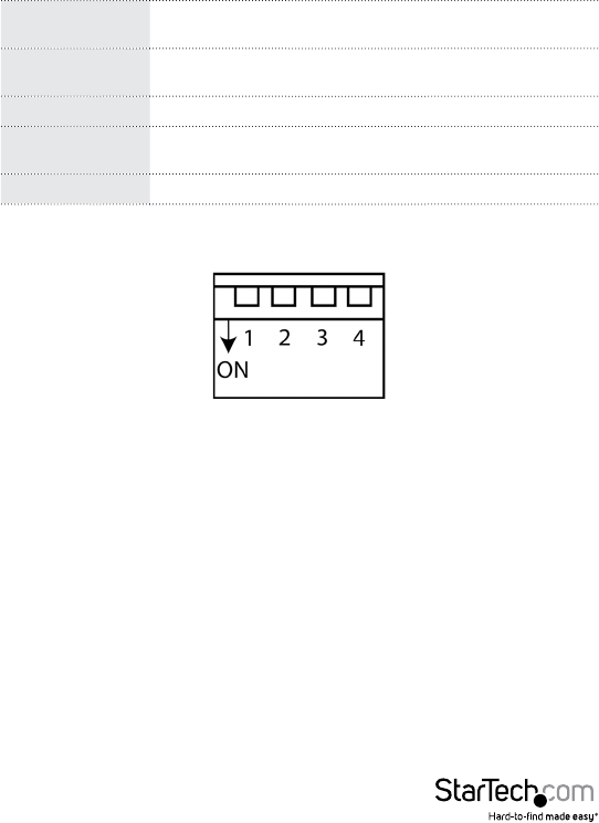
Dip Switch
1. Reserved: This switch currently has no function and is reserved for possible future use.
2. STD/High: When ‘O’ this switch will set the injector for IEEE standard power
injection (15.4W for 802.3af or 30W for 802.3at).
When ‘On’, the injector will provide non‐standard, high power (up to 36W for
802.3at). This high power setting may be required is connecting to more power
hungry “speed dome” PTZ IP camera types.
3. 2 Pair/4 Pair: When ‘O’, this switch will set the injector for IEEE standard power
injection (15.4W for 802.3af or 30/36W for 802.3at), over 2 pairs (4‐wires).
When ‘On’, this switch will enable power injection on all 4 pairs (all 8 wires) of the
UTP cable. This is non‐standard PoE, but it enables an ultra‐high power capability
for 802.3at, providing up to 60W of power. Ultra‐high power may be required by
outdoor cameras that seasonally require fan for cooling in summer, or heater in
winter to maintain proper operating environment for camera elements.
NOTE: When set to 4 pair, DIP switch no.2 is ignored.
4. A Mode/B Mode: In the default mode (A MODE) with switch 4 ‘O’ the PoE is
provided on the 1&2, 3&6 wire pairs.
When ‘On’, the alternative B Mode provides PoE on the alternate pins 4&5, 7&8.