10
MixDream XP
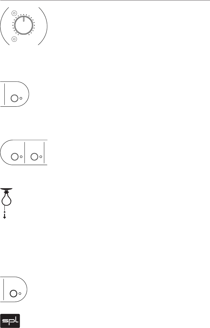
Output Control
The Output control regulates the MixDreamXP output level (at
the Main Outs). Its range extends from -14 dB to +7 dB. With
this Output Control final levels can be ajdusted to accommo-
date subsequent A/D converters. Because the Main Outputs
and Monitor Outputs run in parallel, both outputs are regulated
globally via this control.
Variable Output Switch
The Output Control is activated by the Variable Output switch
situated among the front-left group of switches. When this
Variable Output switch is deactivated, the Input Level remains
unaltered (Unity Gain).
Mono Switches
All MixDreamXP channel pairs (1/2 through 15/16) are by default
panned hard left/right. This configuration is the only sensible
way in which each signal contributing to the stereo sound
canvas can retain its placement and automated characteristics.
However, for mono signals (such as kick, snares, lead vocals
or bass that should appear in the middle of a mix), it would
be a waste to use (in hard L/R panned channels) what would
amount to two required converters for a mono result. In such
cases, each channel pair can be switched to mono mode (red
status LED), so that, for example, there might be a (mono) kick
on channel 1, snare on channel 2 and bass on channel 3, etc.
IMPORTANT: Panning for such instruments in the sequencing
program should place the kick hard left, the snare hard on the
right, and so on.
Expansion
The Expansion Inputs provide an additional XLR stereo input
(see page 9 for details) and can be activated by the Expansion
Inputs Switch in the front-right group of switches. Typically this
stereo input would provide for linking with another MixDream XP
unit.
Control Elements
dB
Output
-
1
4
-
1
3
-
1
2
-
7
-
4
0
3
5
7
Variable
Output
Mono Mono
1/2 3/4
Expansion
Input


