23
Passeq
Equalizer
In our context here, an EQ is in effect a network of frequency lters which changes its output
characteristics depending on frequencies. The common recording studio concept for sound
shaping or correction is the amplitude-based EQ. But owing to the large number of lter
combinations, there are practically too many existing formulations of this design concept
to count. Nonetheless it is sensible to make some general observations that categorize the
most important technical differences among these design concepts.
Passive EQs
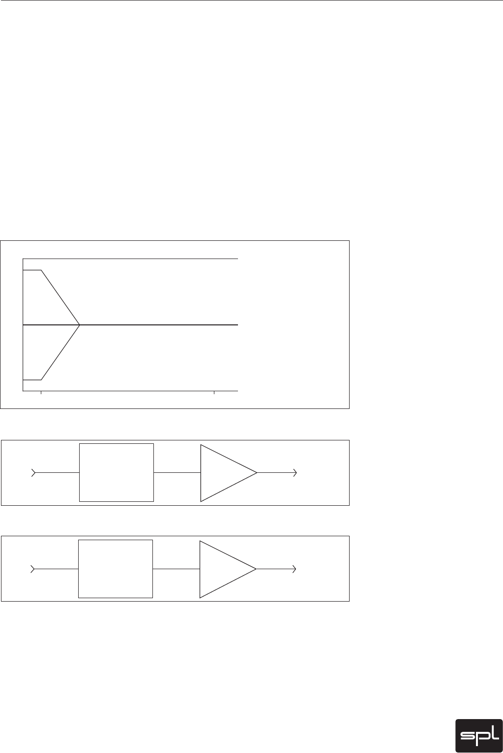
The lters in a passive network employ no intrinsic amplication elements and therefore
need no external power, which means in effect that they can really only cut the energy of
a chosen frequency. In order to expand this capability to include boosting the energy of a
bandwidth (that is, to be able to boost and cut frequencies), the overall lter input signal
level is reduced. Based on this overall reduction and relative to the original input signal, one
can achieve a further cut or boost in the form of a return to that original signal level. Thus
a passive lter is always followed by an amplier which is responsible to regain the initial
energy reduction and restore level balance between the input and output signal levels.
Passive lters react differently than active lters, mostly due to the saturation and loading
characteristics of its coils and condensers. The characteristics of passive lters often are
very advantageous in their ability to create a musically pleasing sonic result: they sound
comparably very smooth and harmonious (please see “Introduction—Advantages of Passive
Filter s” on page 5).
E#
)[ L)[
*OQVUTJHOBMMFWFM
'JMUFSPVUQVUMFWFM
XIFOTFUGPSGMBUSFTQPOTF
#BTTDVUBU)[CZE#
#BTTCPPTUBU)[CZE#
The Basics of Frequency Filtering
*OQVU 0VUQVU
E#V E#VE#V
'JMUFSE#
CPPTU
"NQ
E#V
*OQVU 0VUQVU
E#V E#VE#V
'JMUFSGMBU
E#V
"NQ
E#V
Schematic of a passive frequency
lter
Block diagram of passive lter
set at
Block diagramm of a passive
lter at +18 dB boost


