


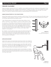


SPEAKER INSTALLATION
All Starlet models install in the same way. The wiring for the Starlet 4 differs from the bi-amplified Starlets 6 and 9. There are
different procedures for mounting in a standard stud depth (2x4 framed wall) and deeper walls (2x6 or deeper). The supplied
foam support block is intended for deeper walls.
The installation of Starlets is straightforward, but it is more difficult than smaller in-walls and following these directions is very
important. Of course, the final result is the best performance available from an in-wall loudspeaker so it is worth the extra effort.
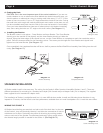
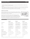
WIRING THE STARLET 4
All Starlets have binding post terminals on both ends of the back box. In the case
of the Starlet 4, they are electrically identical, and allow the connection of wire to
whichever end is easier. Optionally, they allow for bi-wiring by running parallel
wires to each end of the speaker. As mentioned previously, heavy gauge wire in
the shortest length possible is needed for the Starlet 4. (See Diagram 14)
Page 6 Starlet Owner’s Manual
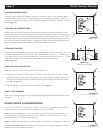
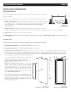
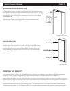
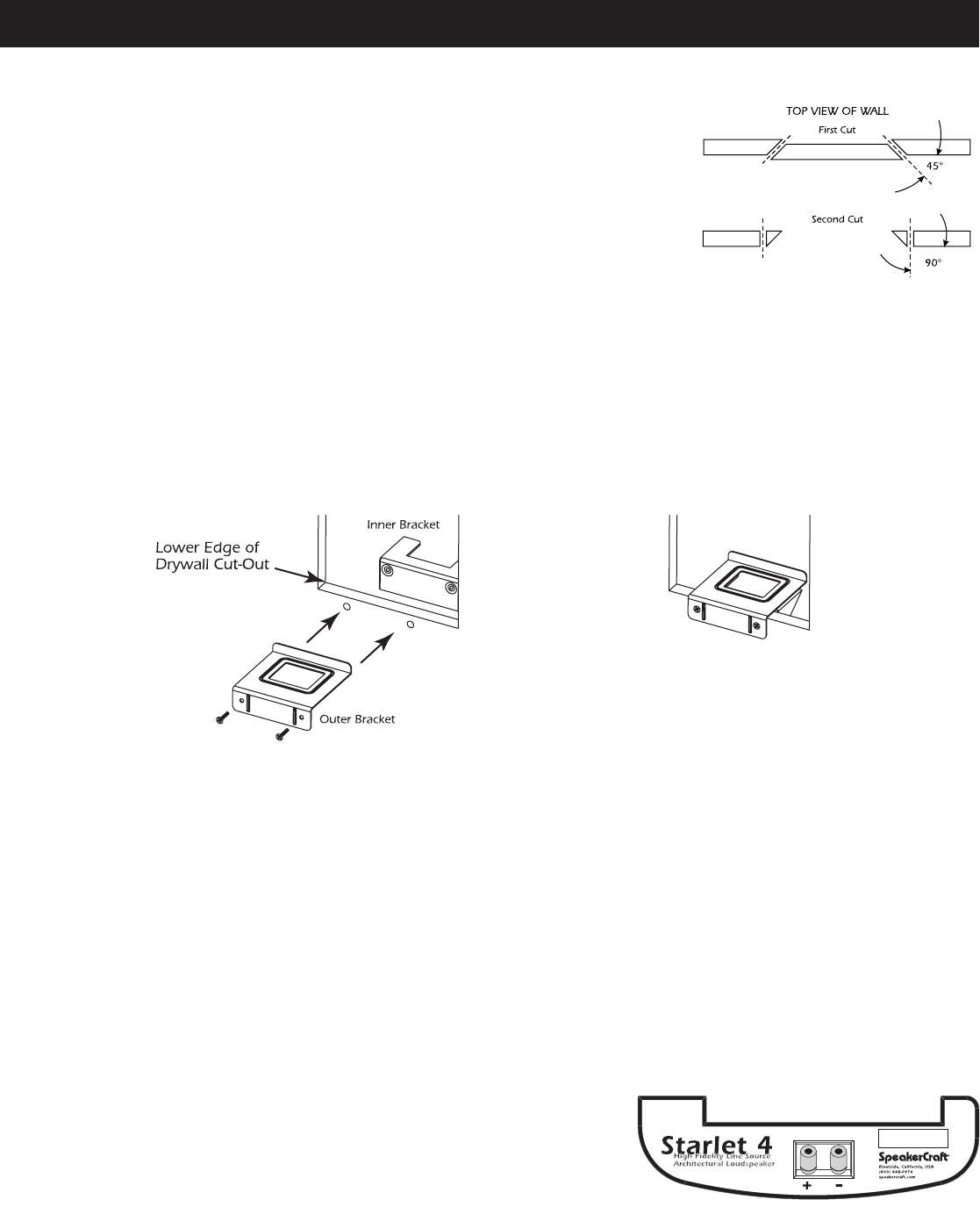
d. Cutting the Hole
CAUTION: This is the most important part of the entire installation. If you are not
certain whether or not an obstruction exists behind the desired mounting area, you
should conduct an obstruction survey by cutting small holes every 10" or 12" in the
center of the cut-out area. Cut at a 45˚ angle towards the inside of the hole. Cutting
the small hole at this angle will make drywall repair much easier as the piece cut out
can be re-installed neatly back into the hole (in the case the location is not suitable).
Once you have determined that there are no obstructions in the desired mounting
area, start cutting the hole at a 90˚ angle to the wall surface. (See Diagram 11)
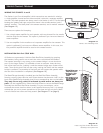
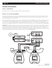
e. Installing the Bracket
The Bracket comes in two pieces - Outer Bracket and Inner Bracket. The Outer Bracket
should go on the outside of the drywall, and the Inner Bracket should go inside the
drywall. Along the lower edge of the drywall cut-out, use the Outer Bracket as a template to mark the screwholes with a
pencil. Drill two clearance holes for the mounting screws. The screws pass through the Outer Bracket and drywall and
tighten into the Inner Bracket. (See Diagram 12)
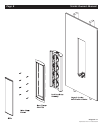
Once assembled, the completed bracket will form a shelf to prevent the Back Box/Driver Assembly from falling into the wall
cavity. (See Diagram 13)
Diagram 11:
Cutting the Hole
Diagram 14:
Starlet 4 Binding Posts
Diagram 12:
Bracket Assembly
Diagram 13:
Completed Bracket