


CAUTION: Be careful NOT to plug the 2-circuit mini plug lead into the +/- 15VDC jack on the
SoundSource by mistake … to do so will smoke the internal SoundSource power circuit!!
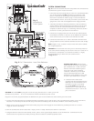
Plug the 2-circuit mini plug lead between the REMOTE OUT jack on the SoundSource and the IR IN jack on the SSL-B.
6. Connect the RCA audio leads (not supplied) between the Auxiliary Sources and the SSL-A. Plug a SpeakerCraft IR emitter (such as the IRE-4.0
illustrated - not included) into the SSL-A IR Out jack and affix the emitter(s) onto the IR Sensor window of the Auxiliary Source(s).
7. When you are sure all connections have been made, plug in the Power Supply for the SoundSource (included) and the PS-1.0 Power
Supply for the SSL-A (included).
8. Turn the SoundSource ON and select AUX 1 input (or Aux 2 if used). Advance the volume to a low level.
9. Using the Remote Control from the Auxiliary Source, point it at the upper triangle window on the SoundSource. Commands from the
remote should now operate the Auxiliary Source(s) that are located in the Main Equipment Room.
Fig. 2
SoundSource
“Links” System
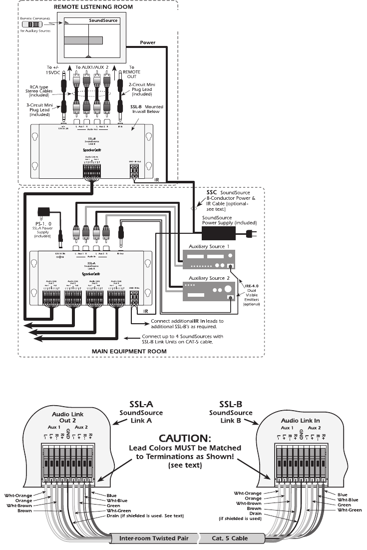
Fig. 3 Cat.5 Connections – Lead Color Reference
SYSTEM CONNECTIONS
Fig. 2 shows how the SSL-A and SSL-B components are connected into
a SoundSource system. Proceed as follows:
1.Pull all the inter-room wiring that you need. It is recommended that
you use the SpeakerCraft
SSC SoundSource 8-conductor cable
(stock # CTL01030) for powering the SoundSource and for the
inter-room IR connections. Refer to page 7 of the SoundSource
Owner’s Manual, Chart A, to be sure you match up the correct wire
gauges and colors with the designated Power Supply terminals.
2. Install the SoundSource following directions in the SoundSource
Owner’s Manual. Before fastening the SoundSource into the wall,
however, be sure all connections between it and the SSL-B are
complete as outlined in steps 3 to 5 following. Mount the SSL-B in
the wall on a surface just below the SoundSource.
3.Connect the 22 gauge inter-room wire of the SSC cable between
the GND/IR In terminals on the SSL-A to the GND/IR Out terminals
of the SSL-B. Be sure to use Green for IR and Black for GND.
4. Connect the inter-room Cat. 5 cable to the Audio Link Aux1/Aux2
spring-loaded EZ-Connect terminals between the SSL-A and SSL-B(s).
Note: Lengths of Cat. 5 cables in excess of 500’ will result in audible
loss of high frequencies.
CAUTION: Be sure that the wire colors you use are exactly matched
to the same terminal markings at both ends of the Cat.5. Failure to do
so will result in out-of-phase or crossed-over channels. It is highly
recommended that you follow the color scheme shown
in
Fig. 3 below:
Shielded Cable Note: The SSL-A and
SSL-B balanced line system, using twisted
pair unshielded Cat. 5 cable, has been
found to work with excellent signal to
noise ratio under many simulated
conditions. However, if you feel there
may be extremely high levels of EMI
interference at the installation site, it may
be safer to pull shielded (Cat. 5) cable.
5. Connect the RCA audio leads
(supplied with the SSL-B) between the
AUX Inputs on the SoundSource and
the Audio Out jacks on the SSL-B.
Plug the
3-circuit mini plug lead
between the +/- 15VDC jack on the
SoundSource and the +/- 15V DC IN
jack on the SSL-B.
SpeakerCraft
®