


SpeakerCraft
®
FUSE 8 AMP 250V
AC 120V 60HZ
SPEAKERSMAIN
INPUT
+ LEFT --
LEFTLEFT
RIGHT RIGHT
CASCADE
OUTPUT
-- RIGHT +
SERIAL NUMBER
Model BB275
AUDIO SENSE
3-30V A/C D/C
TRIGGER
INPUT
3-30V A/C D/C
TRIGGER
INPUT
12V
CONTROL
OUTPUT
CONSTANT
SpeakerCraft
®
FUSE 8 AMP 250V
AC 120V 60HZ
SPEAKERSMAIN
INPUT
+ LEFT --
LEFTLEFT
RIGHT RIGHT
CASCADE
OUTPUT
-- RIGHT +
SERIAL NUMBER
Model BB275
AUDIO SENSE
3-30V A/C D/C
TRIGGER
INPUT
3-30V A/C D/C
TRIGGER
INPUT
12V
CONTROL
OUTPUT
CONSTANT
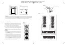
LEFT MAIN
RIGHT MAIN
AMPLIFIER 1
AMPLIFIER 2
TOP VIEW OF WALL
First Cut
Second Cut
Figure 5 Figure 6
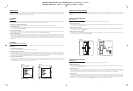
4. Cut the Hole
CAUTION:
This is the most important part of the entire installation. If you are not certain whether or not an obstruction exist behind
the desired mounting area, you should start by cutting a small hole in the center of your penciled mounting hole with a drywall
saw. Cut at a 45˚ angle towards the inside of the hole. See Figure 6. Cutting the small hole at this angle will make drywall repair
much easier as the piece cut out can be installed neatly back into the hole. Once you have determined that there aren’t any
obstructions in your desired mounting location, start cutting the finished hole at a 90˚ angle to the wall surface.
SPEAKER INSTALLATION
The unique integral ten foot mounting system incorporated into each AIM
CINEMA speaker allows for a quick installation by following these easy steps:
1. Remove the grille. It may be necessary to push one or two of the mount-
ing screws and its attached foot towards the baffle and against the inside
surface of the grille to force the grille out of its retaining groove.
2. Attach the speaker cable (observing the proper polarity with your ampli-
fier, + to + and – to –). Make sure the left channel of the amplifier is con-
nected to the left speaker, and the right channel is connected to the right
speaker.
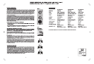
Note: For best bass response be sure to mount your Cinema speaker with the
low frequency (paper cone) drivers towards the bottom as illustrated on
Figure 7
3. BI AMPING
To use your speakers in a bi-amplified configuration, you will need two
separate amplifiers to drive the bass/midrange and treble section of your
speakers. See Figure 9. It will further enhance the loudspeakers perfor-
mance. IMPORTANT: Be sure to remove the jumper wires only when bi-
amplifying the system. See figure 8.
4. Make sure the mounting feet are turned inward to clear the opening, and
insert the speaker into the wall cut-out. Position the speaker into the cut-
out. NOTE: The flange of the speaker is designed to flex and conform to
any small imperfections in the wall’s surface. Tighten the ten screws on the
front of the baffle only enough to make the flange become snug against
the wall. As you tighten the screws, the feet will automatically flip into an
outward position (Figure 7), thereby clamping the drywall between the
feet and the flange. CAUTION: Over tightening may warp the baffle, crack
the wall, cause flange to distort, and make the grille difficult to install.
5. Push the grille firmly into the slot in the speaker baffle.
Figure 7
JUMPER WIRE
Figure 9
BI-AMP CONFIGURATION
Figure 8
3
4
Remove when Bi-Amping
PRINTING INSTRUCTIONS: AIM CINEMA MANUAL - INK: BLACK (1 over 1)
MATERIAL: 80lb Gloss - SIZE: 11" x 17" folded to 8.500” x 11.000”