DESIGN FEATURES
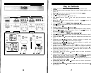
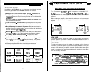
SETTING THE CROSSOVER MODES
Handcrafted in the U.S.A. with mil-spec glass epoxy circuit boards, low-loss
connections, gold plated input connectors, and metal film resistors.
The Soundstream SA.120, 244,
&
245 incorporate a replaceable S.I.P.
electronic crossover for each of their pairs of channels(sub channel only on
SA*245),
as well as the outputs
(SAmI
&
SA*244).
The
SA*120,
244,
&
245
amplifiers can drive a complete system without need of an outboard electronic
crossover.
Darlington High Current Discrete Output Topology
-
Soundstream’s
“overbuilding” of the output
section incorporates Darlington output devices
sandwiched between the circuit board and the heat sink in a design called
ChassisinkTM
to ensure cool, efficient amplifier operation.
Mixed Mono
Capable so you can simultaneously drive a stereo and
mono
load (satellites and subwoofer).
2 Ohm Drive Ability - Soundstream SA Series amplifiers are designed to
drive loads down to 2 Ohms stereo and 4 Ohms bridged.
Built-in Staggered Asymmetrical Crossover
-
Built in 2-way electronic
crossover is designed to send either high or low pass information to the
amplifier. Outputs are included to drive another amplifier with either high or
low pass information
(SA-120
&
SA.244).
Bass EQ
-
Adjustable bass equalization circuit allows you to boost bass by
as much as
+9
dB
at 45 Hz. A built in subsonic filter protects speakers.
Drive Delay” Muted Turn-on/off Circuit
-
A unique circuit which
completely eliminates any amplifier-related turn-on/off noises.
Flexible Input Sensitivity
-
Accepts input voltages
from 100 mV to 2.5 V
(from 40
mV
to 2.5 V on the SA.245 subwoofer channel), which permits
maximum output from amplifier with virtually any source unit.
“Balancing Act” Input Topology for added immunity to ground loops
caused by component and vehicle electrical system interaction.
SA.120
Power
4 ohms
60~x2
Power
2 ohms
9owx2
Bridged Power
4 ohms
180~x1
SA-244
I
60~x4
9owx4
180~x2
SA*245
35wx4+
1oow
x 1
5owx4+-p5q
150wx 1
10
4
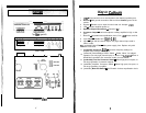
INSTALLATION STEP 1
t
Before installing the amplifier, make certain the switches on the bottom are set
to the correct positions and hole plugs are installed on the bottom of the
amplifier.
CHANNELS 1
&
2 CHANNELS 3
&
4
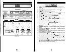
LOW PASS
The low pass crossover is used for sending only low frequency information to
particular speakers (or crossover outputs). Activate the low pass crossover if
you intend to drive subwoofers.
HIGH PASS
The high pass crossover is used for sending only midrange and high frequency
information to particular speakers (or crossover outputs). Activate the high pass
crossover if you intend to drive satellite or coaxial speakers in the system along
with subwoofers. Even if your system does not include subwoofers, it may be
helpful to activate the high pass crossover with smaller speakers to protect them
from low frequency information.
NOTES on the
SA.244
crossover:
+
High Pass
RCA
signai’
oirtlj&t
is
derfved
,frwn
chtpcefs
I
& 2
@&.
To
ac#ust
the
cnksovei
ft$uenc$,
change’
th+.
.~hanneis
I &
2’H&jh
Pass
S,l,
P.
+
Low Pass RCA sign+
outputis
de@&
I@n
;chsinneis’
i,2;3
&4
inputs.
To
a@&
the cmssovei
f#Quency,
change
bo@
Chatyei+
?‘S;
‘2 and
Channels 3
&
4 Low Pass
S.1.P.
k
B&i
Low
Pa&
S.i.P.‘s
tqpt
be
identical
when
usin$j
the Low Pass
RCA,
&puts!
11


