


INSTALLATION STEP 5
TRIDENT PROTECTION CIRCUITRY
Your
Rubicon
amplifier is protected against both overheating and short circuits
by means of main power fuses and the following circuits:
*
Auto
High Current power supply
+
Speaker Output Protection
+ Ground Fault Differential
The input levels are adjusted by means of the individual channel input level
controls located on the front of the amplifier. This is a unique dual-stage circuit
+
Smart Power Supply Thermal Rollback and a Thermal Protection Circuit
that adjusts both level and gain.
This topology maintains better S/N Ratio even
when using sources with minimal output.
In the ideal situation, all components in the audio system reach maximum
undistorted output at the same time. If you send a distorted signal to an amplifier,
it is simply going to amplify distorted information. The same holds true if an
outboard processor or crossover begins to distort before you have maximum
output from the amplifier. By setting all components to reach clipping at the same
time, you can maximize the output of your system. For the
RUBICON
amplifiers,
follow these steps for setting the input levels:
1.
Turn the amplifiers’ input levels to minimum position (counter-clockwise)
2.
Set the source unit volume to approximately
3/4
of full volume.
3.
While playing dynamic source material, slowly increase the amplifiers’ input
level until a near maximum undistorted level is heard in the system.
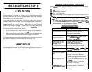
The clipping indicators on the top of the amplifier let you know when the output of
the amplifier is reaching its maximum level, and has begun to clip.
Once the amplifier is installed and the proper levels set, place the front spoiler in
position, and secure it on using the supplied hardware.
T
NOTE:
If
you experience blown main power supply fuses, it is
like9
thaf
the amplifier is seeing a dead short, either in the speaker wire or in
the speaker itself.
Rectijl
the problem before blowing multiple fuses!
DO NOT increase values beyond the original fuse
value1
Doing so
will
void your
warrant and may damage your amplifer.
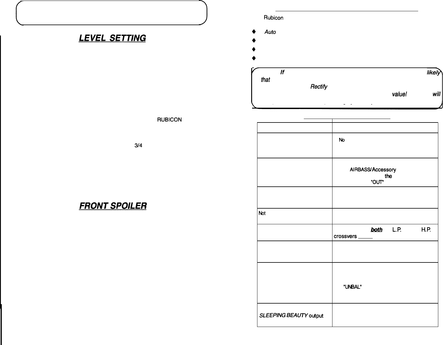
TROUBLESHOOTING
PROBLEM CAUSE
No
Sound and power LED is not
1.
No
power or ground at the amp.
lit
2. No remote turn-on signal
3. Blown fuse near the battery
1. N
O
signal input
No sound, power LED is lit.
2. The AlRBASS/Accessory switch is in the
“IN” position. Remove
the
cover and move
the switch to the
“0l.F
position.
Repeatedly blow amp fuse;
1. Speaker or leads may be shorted
frequent activation of Smart
2. Verify proper speaker load
Power
Supply
Circuit
3. Verify adequate amp ventilation
Not
enough input sensitivity while Be sure both Left and Right input signal
using the Balanced Input
switches are set to the “BAL” position.
Very little output, or output is Make sure that
both
the L.P and the
HP
muffled.
crossvers aren’t engaged
Left and Right “Clip” indicators
Output signal level is too high and the amplifier
lighting
output is clipping. Reduce the level either at
the source or at the input level controls.
Alternator whine while using
Unbalanced RCA inputs
1. Make sure the Right Input Signal Switch is
in the “UNBAL” position.
2.
Try the Left Input Signal switch in the “BAL”
and
“UNBAL”
position: leave the switch in the
quietest setting. This will not effect the
performance of the amplifier.
The Class A 5.2 a.k.a.
Your load on the amplifier is too high (3-4
SLEEPlNG
BEAUTYoutput is ohm stereo) Rewire the amplifier to a
low.
lower impedance load.
15
14