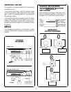
POWER CONNECTIONS
Note: Your amplifier can only be operated from a
12-
Volt Negative Ground electrical system. If your car was
produced before 1970, or if you have any doubts, make
sure of the type of electrical system you have before
making any connections.
Determine the alternator rating of your car and the current
consumption of the car’s other accessories. It may be
necessary to upgrade the alternator or to install a sep-
erate battery and battery isolator.
For power wiring, use Soundstream power cable or an
equivalent premium cable. The plus 12 Volt terminal
of the amp should be connected directly to the posi-
tive terminal of the vehicles battery. Install a fuse in line
between the amplifier and the battery using the follow-
ing fuse for the respective amplifier:
D-20011 . . . . . . . . . . . . . . . . . . . . . . . . . . . . . . . . . . . . . . . . . .
.
.
.
.
.
30 AMP
D-l
001
I
.
.
.
.
.
.
.
.
.
.
.
.
.
.
.
.
.
.
.
.
.
.
.
.
,
.
.
.
.
.
.
.
.
.
.
.
.
.
.
.
.
.
.
.
.
.
.20
AMP
CLASS Al
0011
.
.
.
.
.
.
.
.
.
.
.
.
.
.
.
.
.
.
.
.
.
.
.
.
.
.
.
.
.
.
,
a
a
a..
30 AMP
CLASS
A5011
.
.
.
.
.
.
.
.
.
.
.
.
.
.
.
.
.
.
.
.
.
.
.
.
.
.
.
.
.
.
.
a..
.
.
.
.20
AMP
D-601 I
.
.
.
.
.
.
.
.
.
.
.
.
.
.
.
.
.
.
.
.
.
.
.
.
.
.
.
.
.
.
.
.
.
.
.
.
.
.
.
.
.
.
.
.
.
.
.
.
.
15 AMP
.
If your system is using more than one amplifier, each
amp should be fused seperately.
The Ground terminal of your amplifier should be con-
nected directly to the automobile chassis with the same
gauge wire being used for power. Make sure this wire
is as short as possible to prevent noise in the system.
A nearby bolt can serve as a ground terminal. Make
sure that the wire contacts the chassis, not coated metal
or paint. It is important that the ground connection you
select have minimal noise resistance to the battery
ground post. (A maximum of
.l
ohm resistance should
be present.)
REMOTE
POWER=ON
CONNECTION
If your tuner/deck has a remote power-on control wire,
connect it to the REMOTE terminal on your amplifier.
This is a control line, not a power line, so small wire
(18-20 gauge) is acceptable.
If your tuner/deck has no remote power-on control
labeled as such, but has a power antenna control, it
may be possible to wire the power antenna control to
the REMOTE terminal.
If your tuner/deck has neither a remote power-on control
wire nor a usable power antenna control, it will be
necessary either to connect the REMOTE terminal to a
12 Volt source which is switched by the ignition key or
to connect the REMOTE terminal to a constant 12 Volt
source through an ON/OFF switch you install in series
with the ignition switch in a location accessible to the
driver. Note: If an outboard switch is used, make sure
it is switched off when you leave the vehicle or when
the sound system is not in use otherwise it is possible
to run down your battery.
BEFORE POWERING UP THE SYSTEM
To prevent unnecessary labor, proof all your connec-
tions for shorts and improper connection. Double check
to make sure you have chosen all of the correct ampli-
fier settings.
POWERING UP THE SYSTEM
Once the installation is complete, turn on the system.
The LED indicator on the amplifier should now be lit. If
it did not light up, turn the system off immediately. Proof
wiring and check for shorts or poor connection.
If wiring is okay, check the relay or fuse in the power
line. If blown, replace it with another identical fuse. Also
check the interior power supply fuse. If blown, replace
with a fuse of identical value.
INPUT LEVEL ADJUSTMENT
Input levels are adjusted by means of two independ-
ent controls located between the heat sinks directly
above the appropriate RCA connector, When the
amplifier is being operated in the stereo mode both of
these adjustments are to be used. When bridged, only
the right input control is used.
To set your amplifier levels, begin by turning all level
controls to minimum (counter clockwise) Turn the system
on, and set the volume on your tuner/deck at its mid-
point. Advance the amplifier input level controls until
you have reached your maximum desired listening level
and both channels are in balance.
LINEAR SUBWOOFER EXTENSION
D-20011 AND CLASS A-
10011
The LSE circuit will compensate for the natural
rolloff
of most loudspeakers, and can extend deep bass as
much as one full octave.
The control allows for continuously variable adjustment
over the range from 35 Hz to 280 Hz, of the frequency
at which LSE begins its boost. Below the chosen fre-
quency, the boost is applied at 6 dB per octave. When
properly adjusted, LSE will “linearize” the low end
response of the woofer(s) and provide remarkably
smooth and deep bass. A word of caution: small inex-
pensively constructed woofers may be unable to handle
the equalization which results from setting the LSE to
above 100 Hz. Also, never activate the LSE circuit while
operating the system at high volume. Activate and
deactivate with the system off or at a very low level.
4


