12
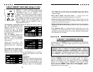
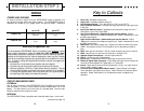
up to 10’ up to 20’
Class A 5.0
Soundstream Power40 or
Power80
Soundstream Power40 only
(4 ga.)
Class A 10.0
Soundstream Power40 only
(4 ga.)
Soundstream Power40 only
(4 ga.)
INSTALLATION STEP 3
WIRING
POWER AND GROUND
To ensure maximum output from your REFERENCE Class A amplifier, use
high quality, low-loss power and ground cables. The REFERENCE Class A
amplifiers will accept up to 4 gauge power and ground cables. Determine
Read this, or sparks will fly!
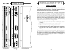
The Soundstream REFERENCE Class A amplifiers have extensive internal
power supply capacitance, called the Ultra-Low ESR Capacitance Bank.
Multiple small input power capacitors act as an internal "stiffening capacitor".
Because of the large amount of internal capacitance, there may be a sizable
spark when connecting the power and ground lead to the amplifier for the first
time. In order to charge the capacitor bank without a spark, we suggest you
do the following:
1. Connect the +12 volt cable to the amplifier and to the battery.
2. Connect one end of the ground cable to the chassis of the vehicle.
3. We have supplied a 150 ohm, 2 watt resistor with the amplifier. One leg
of the resistor has been connected to the ground terminal of the amplifier.
4. To charge the capacitor bank, touch the loose end of the ground cable to
the open leg of the resistor for at least 45 seconds.
CIRCUIT BREAKERS/FUSES
EXTERNAL
Like all audio components, the REFERENCE Class A amplifiers must be fused
near the battery. A fuse or circuit breaker must be located within 18” of the
battery. This will prevent a fire in the event of a shorted cable. See the chart
below to determine the correct fuse value.
INTERNAL
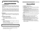
The REFERENCE Class A amplifiers are fused with Maxi-fuses. In the event
(Continued on page 13)
9
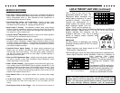
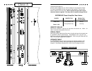
Key to Callouts
1. Fault LED - Indicates a blown fuse.
2. Power LED - Indicates amplifier power on.
3. LSE.Q Bypass Switch - Turns the LSE.Q on ("IN") or off ("OUT").
4. Input Overload Indicators - Indicates the signal input level or input gain level
is too high.
5. Input Level Selector Switch - Selectable input sensitivity range from 0.2-2
Volts RMS, or from 0.5-5 Volts RMS.
6. Left Channel Balanced / Unbalanced Input Selector Switch - Select
"Balanced" to use the 6 pin Balanced signal Input. Select "Unbalanced" to use
the RCA signal inputs.
7. Right Channel Balanced / Unbalanced Input Selector Switch - Select
"Balanced" to use the 6 pin Balanced signal Input. Select "Unbalanced" to use
the RCA signal inputs.
8. Main Fuse - Main power supply fuse. Replace only with the same value fuse.
9. +12V - Connected to a fuse or circuit breaker, then to the battery's positive
post.
10. GND - Main ground connection. Bolt to a clean chassis ground in the vehicle.
11. REM - Remote turn-on input from the head unit. Accepts +12V.
12. Speaker Output Connections - Left and right channels.
13. LSE.Q - Frequency and Q adjustments.
14. Input Level - Independent Left and Right channel input level controls.
15. Balanced Signal Input Connector - 6-pin Balanced signal input connector for
use with the Soundstream BLT Balanced Line Transmitter.
15. Inputs - Right and left channel RCA (Unbalanced ) inputs; only right channel
input is used in "Mono" mode.
16. Coherent Stereo/Bridge/Mixed Mono switch - Select "Bridge" for bridged
mono operation (use right channel input). Select "Stereo" for coherent stereo
operation. Select "Mixed Mono" for simultaneous stereo / bridged mono
operation.


