- 3 -
9. Bass Maximizer Indicator: These two LED indicators flash when the bass maximization
circuit is activated.
10. Input Selector Switch: This switch selects the AUX or CD input.
11. Frequency Band Controls : Adjusts (cut or boost) the level of the three (LOW/ MID/ HIGH)
frequency bands up to +/-18dB
12. Aux Input.
13. Input Grounding Selector: For most systems you can set this switch at the BALANCED
position. In some systems, the source unit may look for a ground through the RCA connectors.
In this event, you should go ahead and change the setting to the UNBALANCED position.
14. Ground Isolation Selector: Occasionally alternator whine may appear in a system
because the source unit and amplifier may use different grounding. To help in this situation,
we have provided alternative grounding selector.
15. Output Voltage: Not all systems are designed the same, some systems are designed
strictly for SPL (Sound Pressure Level) while others are a little more tame. The Bass
Maximizer circuit can either increase or decrease the signal voltage of the Bass Restoration
Circuit. Depending upon your system, you may change this selector switch to a higher or
lower setting to maximize your bass output and protect your speakers.
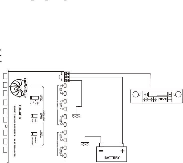
Power connection
Electronic Connections & Wiring
Red
Orange
Black
B+(12V) : Connect to the car battery or other power source.
REMOTE : Connect to remote activating (12V DC)wire of car stereo or equalizer.
GND : Connect to the car chassis for ground connection.


