._-
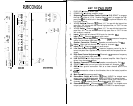
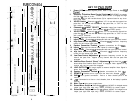
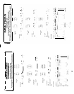
Top View
Front View
60
ttom View
10
1.
2.
3.
4.
5.
6.
7.
8.
9.
IO.
11.
12.
13.
14.
15.
16.
17.
18.
19.
20.
21.
22
23.
24.
25.
26.
27.
28.
29.
30.
31.
32.
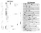
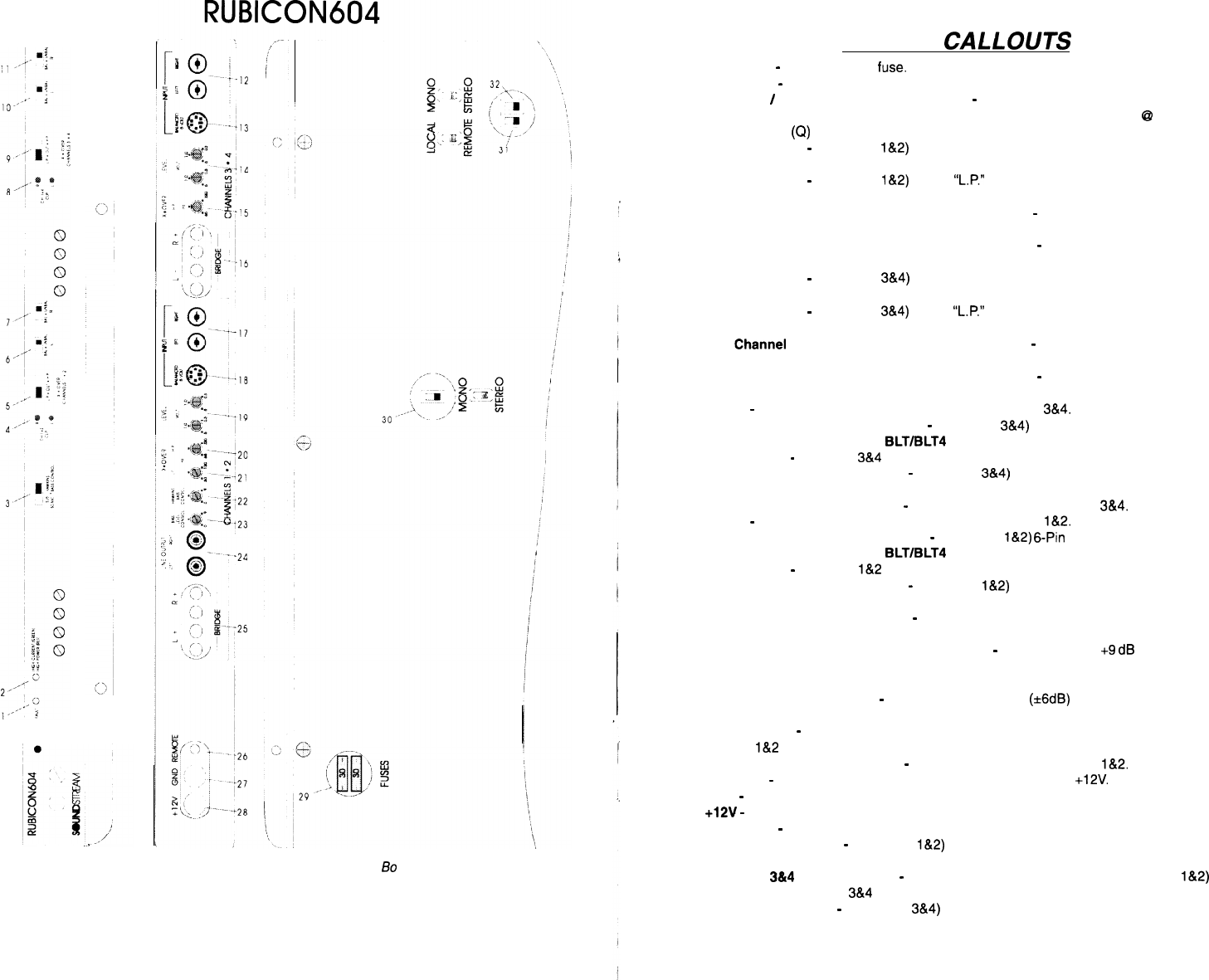
KEY TO CALLOUTS
FUSE LED
-
Indicates blown
fluse.
Power LED
-
indicates amplifier power, either in High Power or Auto High Current.
Subsonic
/
Hawkins Bass Control Switch
-
“SUB SONIC” to engage the Sub Sonic
filter at 13 Hz.
“Hawkins Bass Control” to engage the high pass filter
@
45 Hz with
variable boost
(Q)
for optimum bass for any channel in Low Pass.
Clip Indicators
-
(Channels
l&2)
Indicates the signal output level is too high and the
output stage of the amplifier is clipping.
XOVER Switch
-
(Channels
l&2)
Select
“L.P.”
for use with the internal low pass filter,
“IN” for use with the internal high pass filter, or “OUT” for use with external crossover.
Left Channel Balanced/Unbalanced Input Selector
-
(Ch 1) Select “BALANCED” to
use the 6 pin Balanced signal input. Select “UNBALANCED” to use the RCA signal inputs.
Right Channel Balanced/Unbalanced Input Selector
-
(Ch 2) Select “BALANCED” to
use the 6 pin Balanced signal input. Select “UNBALANCED” to use the RCA signal inputs.
Clip Indicators
-
(Channels
3&4)
Indicates the signal output level is too high and the
output stage of the amplifier is clipping.
XOVER Switch
-
(Channels
3&4)
Select
“L.P.”
for use with the internal low pass filter,
“HP.” for use with the internal high pass filter, or “OUT” for use with external crossover.
Left
#Channel
Balanced/Unbalanced Input Selector
-
(Ch 3) Select “BALANCED” to
use the 6 pin Balanced signal input. Select “UNBALANCED” to use the RCA signal inputs.
Right Channel Balanced/Unbalanced Input Selector
-
(Ch 4) Select “BALANCED” to
use the 6 pin Balanced signal input. Select “UNBALANCED” to use the RCA signal inputs.
Inputs
-
Right and left channel RCA inputs for channels
3&4.
Balanced Signal Input Connector
-
(Channels
3&4)
6-Pin Balanced input connector
for use with the Soundstream
BLT/BLT4
Balanced Line Trasmitter or X.0 crossover.
Input LEVEL
-
Channels
3&4
independent left and right input level control.
High Pass Control Adjustment
-
(Channels
3&4)
crossover frequency control for the
internal high pass filter.
Speaker Connection Terminal
-
Speaker connections for Ch’s
3&4.
Inputs
-
Right and left channel RCA inputs for channels
l&2.
Balanced Signal Input Connector
-
(Channels
l&2)
6-Pin
Balanced input connector
for use with the Soundstream BLT/BLT4 Balanced Line Trasmitter or X.0 crossover.
Input LEVEL
-
Channels
l&2
independent left and right input level control.
High Pass Control Adjustment
-
(Channels
l&2)
crossover frequency control for the
internal high pass filter.
Low Pass Control Adjustment
-
Crossover frequency control for the internal low
pass filter. Applies to any channel with the low pass filter engaged.
Hawkins Bass Control “Boost” Adjustment
-
Varies from 0 to
+9
dB
of boost when
the Hawkins Bass Control is engaged. Note: Applies to any channel with the low pass
filter engaged.
Subwoofer Level Control
-
Additional level control (k6dB) to any channel receiving
information from the low pass filter.
Line Outputs
-
Full range outputs to external amplifier. Note: Signal is driven from
channel
l&2
inputs.
Speaker Connection Terminal
-
Speaker connections for Ch’s
l&2.
REMOTE
-
Remote turn-on input from the head unit. Accepts
+12V.
GND
-
Main ground connection. Bolt to a clean chassis point in the vehicle.
+12V
-
Connected to a fuse or circuit breaker, then to the battery’s positive terminal
Main Fuse
-
Main power supply fuses.
Stereo/Mono Switch
-
(Channels
l&2)
Select “MONO” for bridged mono output (use
right level and RCA input only). Select “STEREO” for stereo output.
Channels
3&4
INPUT SELECT
-
Selectable inputs from internal (from channels
l&2)
or
external (from channels
3&4
local RCA inputs).
Stereo/Mono Switch
-
(Channels
3&4)
Select “MONO” for bridged mono output (use
right level and RCA input only). Select “STEREO” for stereo output.
11


