


Page 2CT10 33-4204 04/06
MOUNTING LOCATIONS
SOUND ADVANCE products provide outstanding per-
formance and economic advantages when installed in
environments with an ambient noise level at or below
75dBA, where the speakers can be placed between 8 and
18 feet above the fl oor, and which are large enough to ac-
commodate at least 4 or more conventional loudspeakers.
When system design requirements indicate speaker to
speaker distances of greater than 40.0 ft., please contact
the factory for additional technical information on such
applications.
SOUND ADVANCE recommends mounting the CT10 in:
Suspended Ceilings
Wood or Metal Stud Ceilings
Most Soffi ts
Retrofi t into almost all standard 8” Loudspeaker Openings
RECOMMENDED ENVIRONMENTS
Indoor or Weather Protected Outdoor
RECOMMENDED FINISH
The fl at Expanded Polystyrene [EPS] loudspeaker surface
may be fi nished with water soluble materials such as latex
paints, to match any decor or color requirement, using
conventional brush-on, roller or airless spray application
systems.
UNPACKING AND INSPECTION
Open the shipping cartons carefully and remove all
contents. Inspect the product and accessories for
damage. Report damage or shortages to SOUND
ADVANCE immediately.
CAUTION: SOUND ADVANCE loudspeakers utilize
a fl at polystyrene material as the sound-radiating
surface. Although it is resistant to mechanical dam-
age and is unaffected by environmental extremes,
care should be observed during handling, to avoid
punctures or other damage.
CAUTION: DO NOT remove the protective cardboard
disk until loudspeaker has been connected and
properly secured.
INSTALLATION
The notes below are intended to provide general informa-
tion and assistance in the installation of a CT10 and its
compatible hardware in a variety of situations, and shall
not be used as a step-by-step installation guide.
Although the CT10 can be installed using most industry-
standard 8” loudspeaker mounting accessories, certain
requirements or restrictions of use may apply. Please
review the following notes and recommendations to assure
all installation prerequisites will be met.
THESE NOTES ARE EXTREMELY IMPORTANT AND
SHOULD BE READ PRIOR TO BEGINNING ANY
INSTALLATION.
Once reviewed, please proceed to the “Loudspeaker
Connection” section.
GENERAL NOTES
•
Make sure loudspeaker mounting confi guration and
installation hardware are compatible and appropriate for
the selected application. System Engineers and Installers
must always consult with the Local Authorities in order to
obtain specifi c requirements of an installation or product
utilization.
• Make sure wiring methods, conduit, clamping, intercon-
nection, sealing and termination procedures comply with
NEC and the appropriate Local, Electrical and Building
Codes.
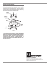
• It is strongly recommended that all ceiling installations
be done using the UMB8-10 Universal Mounting Bracket. It
provides important structural support and is an advisable
safety practice, whether required by code or not.
• A UMB8-10 bracket (or similar) is always required when
installing the CT10 unless the selected backcan or plaster
ring has built-in torsion spring receptacles.
• Hanging straps are normally provided on the PBB8-10
backcan and in most industry standard backcans. These
should be used to attach the backcan (or backcan/bridge
assembly) to the roof or other structural point, to support
and suspend the load. It is good safety practice to use this
option even if not required by local codes.
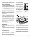
• The loudspeaker carton contains a cutout template that
provides cutting diameters for most installation hardware.
Please review the notes printed in the packaging carton
to determine the proper hole size.
• If working on a retrofi t installation using torsion spring
mounting hardware, insure that existing backcans have
suffi cient room for the torsion springs to open when