


3
TABLE OF CONTENTS
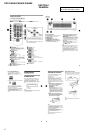
1. GENERAL
........................................................................... 4
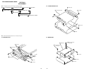
2. DISASSEMBLY
2-1. Sub Panel Assy .................................................................. 10
2-2. CD Mechanism Block ....................................................... 10
2-3. Main Board ....................................................................... 10
2-4. Heat Sink ...........................................................................11
2-5. Chassis (T) Assy................................................................ 11
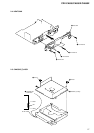
2-6. Lever Section.....................................................................12
2-7. Servo Board....................................................................... 12
2-8. Arm Roller Assy ................................................................13
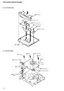
2-9. Chassis (OP) Assy .............................................................13
2-10. Optical Pick-up Block ....................................................... 14
3. DIAGRAMS
3-1. IC Pin Descriptions ........................................................... 15
3-2. Block Diagram –CD Section–...........................................23
3-3. Block Diagram –Tuner Section– .......................................24
3-4. Block Diagram –Display Section–.................................... 25
3-5. Circuit Boards Location .................................................... 26
3-6. Printed Wiring Boards –CD Mechanism Section–............28
3-7. Schematic Diagram –CD Mechanism Section (1/2)– ....... 30
3-8. Schematic Diagram –CD Mechanism Section (2/2)– ....... 31
3-9. Printed Wiring Boards –Main Section– ............................ 32
3-10. Schematic Diagram –Main Section (1/4)–........................ 34
3-11. Schematic Diagram –Main Section (2/4)–........................ 35
3-12. Schematic Diagram –Main Section (3/4)–........................ 36
3-13. Schematic Diagram –Main Section (4/4)–........................ 37
3-14. Printed Wiring Board –Sub (CD) Section– ....................... 38
3-15. Schematic Diagram –Sub (CD) Section–..........................39
3-16. Printed Wiring Board –Key Section– ................................40
3-17. Schematic Diagram –Key Section–...................................41
4. EXPLODED VIEWS
4-1. Chassis Section ................................................................. 46
4-2. Front panel Section ........................................................... 47
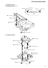
4-3. CD Mechanism Section (1)............................................... 48
4-4. CD Mechanism Section (2)............................................... 49
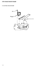
4-5. CD Mechanism Section (3)............................................... 50
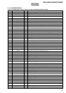
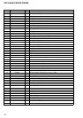
5. ELECTRICAL PARTS LIST ........................................ 51
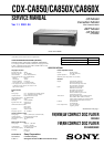
CDX-CA850/CA850X/CA860X
Ver 1.1 2001. 04