


27
XR-CA600/CA600V/CA600X
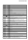
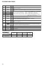
Pin No. Pin Name I/O Description
40
TELATT I Telephone attenuate signal input At input of “H”, the signal is attenuated by –20 dB
41
NIH I Not used (fixed at “H”)
42 BUSSO
O Serial data output to the SONY bus interface (IC581)
43 BUSSI
I Serial data input from the SONY bus interface (IC581)
44 BUSCKO
O Serial data transfer clock signal output to the SONY bus interface (IC581)
45 IIC SIO I/O
Two-way data IIC bus with the FM/AM tuner unit (TU1), RDS decoder (IC51) and electrical
volume (IC331)
46
NCO O Not used (open)
47 IIC CKO O
IIC bus clock signal output to the FM/AM tuner unit (TU1), RDS decoder (IC51) and electrical
volume (IC331)
48 AMPON O
Standby on/off control signal output to the power amplifier (IC751)
“L”: standby mode, “H”: amplifier on
49 AMPATT
O Muting on/off control signal output to the power amplifier (IC751) “L”: muting on
50 ATT
O Audio line muting on/off control signal output “H”: muting on
51
NCO O Not used (open)
52 AMSON O
Tape auto music sensor control signal output to the CXA2509AQ (IC301)
“L”: auto music sensor on
53 F/ROUT O
Forward/reverse control signal output to the CXA2509AQ (IC301)
“L”: reverse direction, “H”: forward direction
54
MTLON O
METAL control in/out terminal
At initial mode: valid/invalid selection input of METAL function (valid at “L” input)
At normal mode: METAL on/off control signal output to the CXA2509AQ (IC301)
(METAL on at “H” output)
55 TAPATT O
Tape muting on/off control signal output to the CXA2509AQ (IC301) “H”: muting on
Active at ATA, FF/REW mode
56
NCO I/O Dolby control in/out terminal Not used (pull down)
57 AMSIN I
Whether a music is present or not from CXA2509AQ (IC301) is detected at auto music sensor
“L”: music is present, “H”: music is not present
58
4VPRE
I
4V PREOUT setting terminal “L”: 4V PREOUT on Fixed at “H” in this set
59 VOLATT
O
Pre amplifier muting on/off control signal output to the electrical volume (IC331)
“L”: muting on
60 to 64
NCO O Not used (open)
65
FL_W
I
Internal flash memory data write mode detection signal input terminal “L”: data write mode
Not used (open)
66 TESTIN
I Setting terminal for the test mode “L”: test mode, normally fixed at “H”
67 RCIN1
I Rotary remote commander shift key input terminal “L”: shift key on
68 to 73
NCO O Not used (open)
74 EEP SIO I/O Two-way data bus for tuner EEPROM with the FM/AM tuner unit (TU1)
75
EEP CKO I/O
Two-way bus clock signal for tuner EEPROM with the FM/AM tuner unit (TU1)
76
COLSEL
I
Setting terminal for the illumination color
“L”: amber, “H”: green Fixed at “L” in this set
77 NCO O Not used (open)
78
DOORSW I
Front panel open/close detection signal input “L” is input when the front panel is closed
79
DOORIND
O
LED drive signal output of the MD disc slot illumination and Z indicator (LED810, LSW810)
“H”: LED on “H” is output to turn on the LED when front panel is opened
80, 81
RE IN1, RE IN0
I Dial pulse input of the rotary encoder (RE901) (for VOLUME control)
82 AD ON
O
A/D converter power control signal output terminal
When the KEYACK (pin wh) that controls reference voltage power for key A/D conversion input
is active, “L” is output from this terminal to enable the input