


8
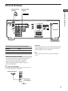
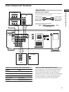
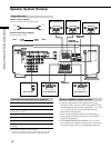
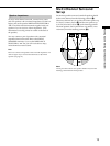
Hooking Up the Components
WIRELESS
REAR
SPEAKER
4 Ω 8 Ω
+
+
–
–
–
+
+
–
–
+
+
–
SPEAKERS
FRONT
REAR CENTER
WOOFER
AUDIO
OUT
VIDEO
OUT
VIDEO
IN
VIDEO
OUT
VIDEO
IN
DVD / LD IN
VIDEO
OUT
VIDEO
IN
L
R
SIGNAL
GND
COAXIAL
AM
AUDIO
IN
L
R
AUDIO
OUT
AUDIO
IN
AUDIO
OUT
AUDIO
IN
CTRL A1
y
y
ANTENNA
S-LINK
VIDEO
IN
AUDIO
IN
OPTICAL
IMPEDANCE
SELECTOR
FRONT
IN
PHONO
IN
CD
INRECOUT
TAPE/MD
FM
75Ω
R
AA
BB
L
RL
RL
RL
VIDEO
OUT
R
AUDIO
OUT
OUTPUT
L
DIGITAL
OPTICAL
OUTPUT
VIDEO 2
MONITORMONITOR
VIDEO 1
TV/
DBS
DVD/
LD
DIGITAL
AC OUTLET
DVD/LD
VIDEO IN
DIGITAL
DVD/LD IN
(COAXIAL)
(OPTICAL)
AC-3 RF
OUT
VIDEO OUT
EQ
ON/OFF
INPUT
MODE
VIDEO 1
DIRECT
TUNING
BASS
BOOST
SOUND FIELD
GENRE MODE
VIDEO 2 DVD/LD TV/DBS
MUTING
BALANCE
LR
5
0
1
3
9
7
46
2
8
10
¥
¥
¥
¥
¥
¥
¥
¥
¥
¥
¥
¥
¥
¥
¥
¥
¥
¥
¥
¥
¥
¥
¥
¥
¥
¥
¥
¥
¥
¥
¥
PHONES
SPEAKERS
SET UP
SURROUND
EQUALIZER
CURSOR MODE
MEMORY
PRESET
—
TUNING
+
A
OFF
A
+
B
B
g
MASTER VOLUME
DISPLAY
FM/AMFM MODE
—
TUNING
+
SLEEP
INDEX
5.1/DVD
INPUT
BASS
BOOST
EQ
SOUND FIELD
ON/OFF
FUNCTION
MULTI CHANNEL DECODING
TAPE/MD CD TUNER PHONO
SHIFT
1
6
2
7
3
8
4
9
5
0
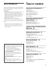
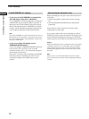
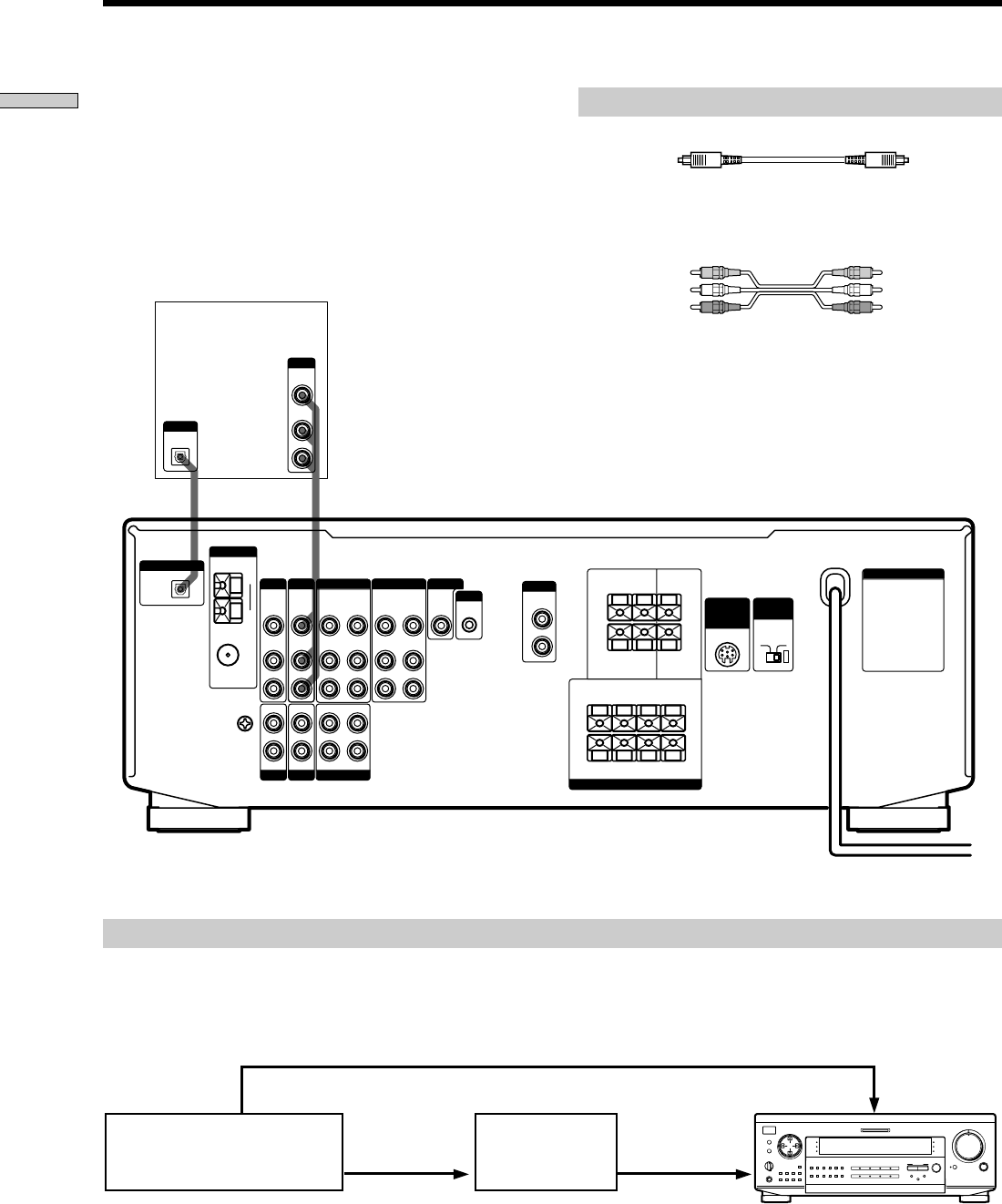
DVD player (etc.)
Required cords
Optical digital cords (not supplied)
Audio/video cords (not supplied)
When connecting a cord, be sure to match the color-coded pins to
the appropriate jacks on the components.
Connect the digital output jacks of your DVD player to
the receiver’s digital input jacks to bring the multi channel
surround sound of a movie theater into your home. To
enjoy full effect of multi channel surround sound, five
speakers (two front speakers, two rear speakers, and a
center speaker) and a subwoofer are required. You can
also connect an LD player with an RF OUT jack via an RF
demodulator, like the Sony MOD-RF1 (not supplied).
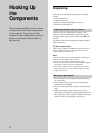
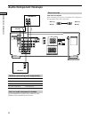
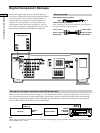
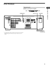
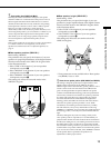
Digital Component Hookups
Please note that you cannot connect an LD player’s AC-3 RF OUT jack directly to this unit’s digital input jacks. You must
first convert the RF signal to an optical digital signal. Connect the LD player to the RF demodulator, then connect the RF
demodulator’s optical digital output to this unit’s OPTICAL DVD/LD IN jack. Refer to the instruction manual supplied
with your RF Demodulator for details on AC-3 RF hookups.
Example of LD player connected via an RF demodulator
RF demodulatorLD player
Black Black
Yellow (video) Yellow (video)
White (L/audio) White (L/audio)
Red (R/audio) Red (R/audio)
DIGITAL
DVD/LD IN
OPTICAL
Note
When making connections as shown above, be sure to set INPUT MODE (3 on page 21) manually. This unit may not operate correctly if
INPUT MODE is set to “AUTO.”