


3
About This Manual
The instructions in this manual are for models
STR-DE475 and STR-K402. Check your model number by
looking at the lower right corner of the front panel.
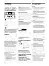
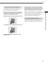
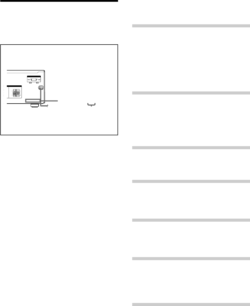
About area codes
The area code of the player you purchased is shown on the
lower portion of the rear panel (see the illustration below).
Any differences in operation, according to the area code, are
clearly indicated in the text, for example, “Models of area
code AA only”.
Conventions
• The instructions in this manual describe the controls on
the receiver. You can also use the controls on the
supplied remote if they have the same or similar names
as those on the receiver.
• The following icon is used in this manual:
z Indicates hints and tips for making the task easier.
This receiver incorporates Dolby
* Digital and Pro Logic
Surround and the DTS** Digital Surround System.
*
Manufactured under license from Dolby Laboratories.
“Dolby”, “AC-3”, “Pro Logic” and the double-D symbol a are
trademarks of Dolby Laboratories.
Confidential unpublished Works. © 1992-1997 Dolby Laboratories.
All rights reserved.
**
Manufactured under license from Digital Theater Systems, Inc. US
Pat. No. 5,451,942, 5,956,674, 5,974,380, 5,978,762 and other
world-wide patents issued and pending. “DTS” and “DTS Digital
Surround” are registered trademarks of Digital Theater Systems, Inc.
Copyright 1996, 2000 Digital Theater Systems, Inc. All Rights
Reserved.
TABLE OF CONTENTS
Hooking Up the Components 4
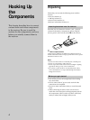
Unpacking 4
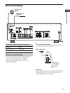
Antenna Hookups 5
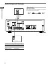
Audio Component Hookups 6
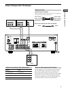
Video Component Hookups 7
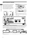
Digital Component Hookups 8
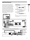
MULTI CH IN Hookups 9
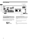
Other Hookups 10
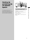
Hooking Up and Setting Up the
Speaker System 11
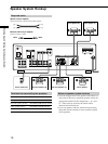
Speaker System Hookup 12
Performing Initial Setup Operations 14
Multi Channel Surround Setup 15
Before You Use Your Receiver 19
Location of Parts and Basic
Operations 21
Front Panel Parts Descriptions 21
Enjoying Surround Sound 24
Selecting a Sound Field 25
Understanding the Multi-Channel Surround Displays 28
Customizing Sound Fields 30
Receiving Broadcasts 34
Direct Tuning 36
Automatic Tuning 36
Preset Tuning 37
Other Operations 38
Naming Preset Stations and Program Sources 39
Recording 39
Using the Sleep Timer 40
Adjustment Using the SET UP Button 41
Additional Information 42
Troubleshooting 42
Specifications 44
Glossary 46
Settings Using SURR, LEVEL, and SET UP buttons 47
Remote Button Description 48
Index 51
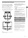
FRONT
120V
240V 220V
CENTER
RL
RL
VOLTAGE SELECTORVOLTAGE SELECTOR
R
S
R
S
IMPEDANCE USE 8 – 16
Ω
IMPEDANCE USE 8 – 16
Ω
4-XXX-XXX-XX AA
Area code