


13
US
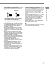
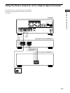
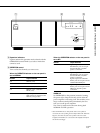
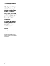
Location of Parts and Basic Operations
1
2 3
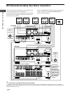
STANDBY
OPERATION
WARM UP
EXTRA 2ch
/
BTL EXTRA 2ch5ch
/
BTL 2+1 ch
4ch
/
BTL 2ch
3ch
2ch
BTL 2ch BTL 2+1ch BTL EXTRA 2ch
5ch WARM UP EXTRA 2ch4ch3ch2ch
U
2 Operation indicators
Light to indicate the operation mode selected with the
OPERATION control. Blink if you select a mode that
cannot be used.
3 OPERATION control
Turn to select the channels you want to use.
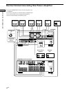
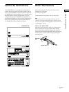
When the OPERATION selector on the rear panel is
set to NORMAL
Position Output Channels
2ch FRONT (L/R)
3ch FRONT (L/R) + CENTER
4ch FRONT (L/R) + REAR (L/R)
5ch FRONT (L/R) + CENTER +
REAR (L/R)
EXTRA 2ch Signals input to the EXTRA 2ch
INPUT jacks are output from the
FRONT (L/R) speakers.
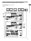
When the OPERATION selector on the rear panel is
set to BTL
Position Output Channels
BTL 2ch Signals input to the FRONT or
REAR INPUT jacks are output
from the FRONT (L/R) BTL
speaker connections.
BTL 2ch + 1ch* Signals input to the FRONT or
REAR INPUT jacks are output
from the FRONT (L/R) BTL
speaker connections.
Signals input to the CENTER
INPUT jacks are output from the
CENTER SPEAKER jacks.
BTL EXTRA 2ch Signals input to the EXTRA 2ch
INPUT jacks are output from the
FRONT (L/R) BTL speaker
connections.
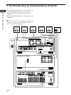
WARM UP
Set OPERATION to this position (instead of turning
the power off) to keep the circuitry warm when the
power amplifier is not being used. This enables you to
enjoy excellent sound quality immediately the next
time you use the power amplifier.
The warm up mode works the same during both
NORMAL and BTL operation.
* When OPERATION is in this position and a center speaker is
connected, the center speaker gain level drops about 6 dB. When this
happens, raise the level of the center speaker on the AV control
amplifier (TA-E9000ES, etc.) connected to this amplifier and adjust
the volume accordingly.