


51
Other Operations
CONTROL A1 Control
System
Getting Started
This section explains the basic functions of the
CONTROL A1
Control System. Certain components
have special functions, like “CD Synchro Dubbing” on
cassette decks, that require CONTROL A1
connections. For detailed information regarding
specific operations, be sure to also refer to the
Operating Instructions supplied with your
component(s).
The CONTROL A1
Control System was designed to
simplify the operation of audio systems composed of
separate Sony components. CONTROL A1
connections
provide a path for the transmission of control signals
which enable automatic operation and control features
usually associated with integrated systems.
Currently, CONTROL A1
connections between a Sony
CD player, amplifier (receiver), MD deck and cassette
deck provide automatic function selection and
synchronized recording.
In the future the CONTROL A1
connection will work as
a multifunction bus allowing you to control various
functions for each component.
Notes
• The CONTROL A1 Control System is designed to maintain
upward compatibility as the Control System is upgraded to
handle new functions. In this case, however, older components
will not be compatible with the new functions.
• Do not operate a 2 way remote control unit when the
CONTROL A1 jacks are connected via a PC interface kit to a
personal computer running “MD Editor” or similar application.
Also, do not operate the connected component in a manner
contrary to the functions of the application, as this may cause
the application to operate incorrectly.
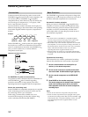
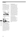
CONTROL A1 and CONTROL A1 compatibility
The CONTROL A1 control system has been updated to the
CONTROL A1 which is the standard system in the SONY
300 disc CD changer and other recent Sony components.
Components with CONTROL A1 jacks are compatible with
components with CONTROL A1 , and can be connected to
each other. Basically, the majority of the functions available
with the CONTROL A1 control system will be available with
the CONTROL A1 control system.
However, when making connections between components
with CONTROL A1 jacks and components with CONTROL
A1 jacks, the number of functions that can be controlled
may be limited depending on the component. For detailed
information, refer to the Operating Instructions supplied with
the component(s).
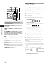
Selecting the color of the on-screen
display (STR-DE945 only)
Select the color of the on-screen display. You can
select either COLOR or MONOCHROME. The color of the
on-screen display is set to COLOR by default.
1 Press SET UP.
2 Press the cursor buttons ( or ) to select “OSD
COLOR”.
3 Turn the jog dial to select “COLOR” or
“MONOCHROME”
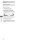
Set the display to turn off
This parameter lets you specify whether or not the display
turns off when you press the DIMMER button several
times. When “WIDE” is selected, you can set the display
to turn off, but when “NARROW” is selected, you cannot
set the display to turn off. The default setting is set to
“NARROW”.
1 Press SET UP.
2 Press the cursor buttons ( or ) to select “DIMM.
RANGE”.
3 Turn the jog dial to select “NARROW” or “WIDE”.