


24
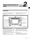
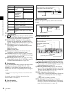
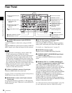
Front Panel
Chapter 2 Names and Functions of Parts
.
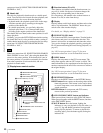
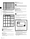
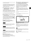
B Data indication: Appears when the input signals are
non-audio signals.
C Mixing: Displays the input channels used for
audio mixing. (These channels are selected with setup
menu item 819 AUDIO INPUT ARRANGE.)
D Monitor channel: Displays the audio monitoring
channels set with MONITR L and MONITR R on
page P2 AUDIO of the function menu (see page 49).
E Audio channel: Displays the audio channels.
Also indicates preset or variable mode by its color
(see page 18).
White: Preset mode
Green: Variable mode
F Reference level: Displays the reference level for
recording as set in the maintenance menu.
G Level bars: Display the audio recording or playback
levels of channels 1 to 8. The OVER indicators light
when the audio level exceeds 0 dB.
H Meter display mode: Displays the audio level meter
display mode selected with AU METER on page P4
AUDIO of the function menu (see page 50).
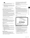
b Function menu
Use the PAGE/HOME button to display this menu, and to
switch between the pages (HOME, P1 to P7, (P8)
1)
,
(HOME2)
1)
) of the menu. Each page has three to six
setting items. Press the corresponding button to change a
setting.
1) If a menu item is assigned using maintenance menu item M38: F-KEY
CONFIG
For details, see page 48 “Basic Operations of the
Function Menu” in Chapter 3.
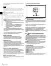
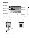
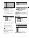
c Clip information
Displays clip information.
d Recording format
Displays the system frequency and the video and audio
formats.
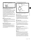
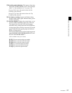
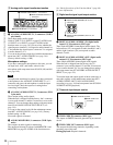
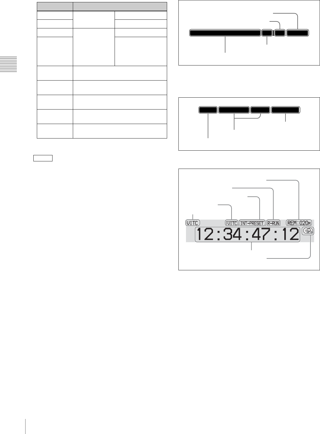
e Time data display area
A Remaining disc recording capacity: Displays the
amount of recording capacity remaining on the disc.
B Rec Run/Free Run: Displays the timecode run mode.
The run mode is set with RUN MODE on page P5 TC
of the function menu (see page 51).
C Timecode generator mode: Displays the timecode
source and generation method (preset or regenerate).
These are set with PRST/RGN and TCG on page P5
TC of the function menu (see page 51).
D VITC: Lights in the following cases.
• When VITC is read in playback mode. (This has no
relations to the display in the time data display
area.)
• When VITC recording is possible.
E Time data type: Displays the type of time data
displayed in the time data display area. The type of
time data is selected with CNTR SEL on the HOME
page of the function menu (see page 48).
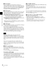
Display Input signal
ANA-1 Analog audio
signal
Channel 1, 3
ANA-2 Channel 2, 4
MIC-1 Input signal from
the microphone
connected to
ANALOG
AUDIO INPUT
connector
Channel 1, 3
MIC-2 Channel 2, 4
AES/EBU AES/EBU format digital audio signal
(flashes when there is no input signal)
HD-SDI HDSDI audio signal (flashes when
there is no input signal)
SD-SDI SDSDI audio signal (flashes when
there is no input signal)
SG Test signal from the internal signal
generator
No indication Undefined audio signal, or no audio
input
F1600
PDW-HD1500 001/001 000:00
All remaining clips or clip list playback time
Total number of clips recorded on disc
Clip name
Number of current clip
8CH-24BIT
59.94i HD422-1080 50Mbps
System frequency
Video format
Audio format
A Remaining disc recording capacity
B Rec Run/Free Run
C Timecode generator mode
D VITC
E Time data type
F Time data
G Recording mode indication