


16
MZ-NH1
SECTION 5
ELECTRICAL ADJUSTMENTS
1. PRECAUTIONS FOR ADJUSTMENT
1. Adjustment must be done in the test mode only. After adjusting,
release the test mode. A key having no particular description
in the text, indicates a set key.
2. Use the following tools and measuring instruments.
• Digital voltmeter
• Regulated dc power supply (two sets)
• Thermometer (using the “Setting The Temperature Correction
Value”)
• Laser power meter
• CD adjustment disc TDYS-1 (Part No. : 4-963-646-01)
• MD1/HiMD1 hybrid adjustment disc MDW-74/GA1
(Part No. : 4-229-747-01)
• Hi-MD3 adjustment disc HMD1GSDJ
(Part No. : 7-819-098-37) *1
• Remote commander in accessories (with LCD)
• Battery charging stand and AC adapter in accessories
• Lithium-ion battery (LIP-4WM) in accessories
(full charged)
• PC application software for test mode
“TestMode_Enter_For_NH1_NH3D_Ver***.exe” *2
• USB cable
*1) Hi-MD3 adjustment disc (HMD1GSDJ) is consumable.
Therefore if it is used 400 times, exchange it for a new.
*2) Use the newest version every time.
Copy the whole folder of this program to your PC.
Operating system: Windows 2000, Windows XP
When using this application, the SonicStage Ver. 2.0 or 2.1 is
necessary, and install it in your PC in advance.
3. Unless specified otherwise, use the AC adaptor and battery
charging stand in accessories.
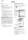
2. ADJUSTMENT SEQUENCE
Adjustment must be done with the following order.
Adjustment order:
1. Entering the test mode
2. Initialize the adjustment value
3. Setting the temperature correction value
4. Power supply voltage adjustment
5. Charge function check
6. Laser power check
7. Setting the adjustment values
8. Servo Overall adjustment
9. Resume clear
10. Releasing the test mode
3. ADJUSTMENT OF THE EACH ITEM
3-1. Entering The Test Mode
Refer to the “SECTION 4. TEST MODE”.
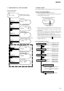
3-2. Initialize The Adjustment Value
Procedure:
1. In the test mode (Display Check mode), press the [VOL--] key
to enter the Overall adjustment mode.
2. Press the [T MARK] key and display “911 ResOK?”.
3. Press the X key to display “911 Reset!” and initialize the
adjustment values.
4. Press the x key and back to Display Check mode.
3-3. Setting The Temperature Correction Value
Procedure:
1. In the test mode (Display Check mode), press the [VOL+] key
to enter the Manual mode.
2. Press the [FF] key twice, and press the [VOL+] key twice to
display as follows.
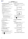
Display of the remote commander
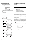
3. Press the [FF] key once to select the item number 0131 and
display as follows.
Display of the remote commander
4. Measure the ambient temperature.
5. Adjust with [VOL+]/[VOL--] keys so that the adjusted value
(hexadecimal value) becomes the ambient temperature.
(example: 25 °C = 19h)
6. Press the X key to write the adjusted value.
7. Press the x key four times and back to the Display Check
mode.
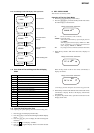
3-4. Power Supply Voltage Adjustment
Adjustment must be done with the following order.
3-4-1. Setting
Procedure:
1. Apply the voltage of 3.7 V to the battery terminals, and enter
the test mode (Display Check mode).
2. Press the [VOL+] key to enter the Manual mode.
3. Press the [VOL+] key twice to display as follows.
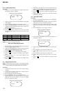
Display of the remote commander
4. Press the [FF] key once, press the [VOL+] key once, and press
the [FF] key once again to display as follows.
Display of the remote commander
5. Repeat the next procedures (3-4-2. PwrAdj Adjustments), and
adjust all contents of “table 3-4-1. PwrAdj Specifications”.
130
Temp
131
SetTmp **
adjustment value (hexadecimal)
002
POWER
210
PwrAdj
Ver 1.1