1-19
MVE-9000 IM
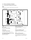
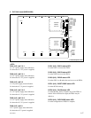
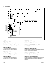
<LEDs on the CPU-DR module> (G-2), (G-5)
Refer to <LED on the CPU-DR module> in “1. CA-
54CFA Board”.
<Switches on the CPU-DR module> (G-2), (G-5)
Refer to <Switches on the CPU-DR module> in “1. CA-
54CFA Board”.
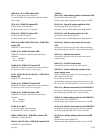
TP501 (H-5) :
++
++
+1.5 V-1 check terminal
+1.5 V-1 measuring terminal.
TP502 (H-5) :
++
++
+2.5 V-1 check terminal
+2.5 V-1 measuring terminal.
TP503 (H-5) :
++
++
+3.3 V check terminal
+3.3 V measuring terminal.
TP504 (H-5) :
++
++
+1.5 V-2 check terminal
+1.5 V-2 measuring terminal.
TP505 (H-5) :
++
++
+2.5 V-2 check terminal
+2.5 V-2 measuring terminal.
TP506 (H-5) :
++
++
+12 V check terminal
+12 V measuring terminal.
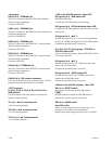
TP601 (A-1) : CK (clock for video signal) terminal
Used when checking the clock for video signal.
TP3801 (H-1) : DBG 3 A check terminal
Used for design purpose.
TP3802 (H-1) : DBG 2 A check terminal
Used for design purpose.
TP3803 (H-1) : DBG 1 A check terminal
Used for design purpose.
TP3804 (H-1) : DBG 0 A check terminal
Used for design purpose.
TP3901 (H-6) : DBG 3 B check terminal
Used for design purpose.
TP3902 (H-6) : DBG 2 B check terminal
Used for design purpose.
TP3903 (H-6) : DBG 1 B check terminal
Used for design purpose.
TP3904 (H-6) : DBG 0 B check terminal
Used for design purpose.


